Fuji 2MBI75N-120 IGBT Module: A Technical Review for Reliable Power Conversion
Fuji Electric 2MBI75N-120 Dual IGBT Module Technical Review
Introduction and Core Highlights
The Fuji Electric 2MBI75N-120 is a dual IGBT module from the N-series, offering a robust and field-proven solution for power conversion systems. This component is engineered to deliver a balanced performance between conduction and switching losses, focusing on reliability for industrial applications. It integrates two IGBTs in a half-bridge configuration within a standard package, simplifying thermal management and mechanical assembly.
- Core Specifications: 1200V | 75A | VCE(sat) 2.2V (typ)
- Key Advantages: Low saturation voltage minimizes conduction losses, while the package design features low internal stray inductance for cleaner switching.
This module’s established design provides a dependable foundation for systems where long-term operational stability is a primary engineering goal.
Download Official Datasheet (PDF)
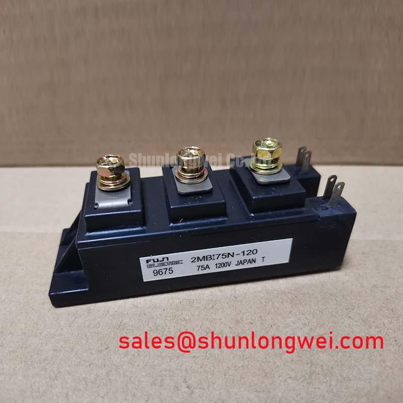
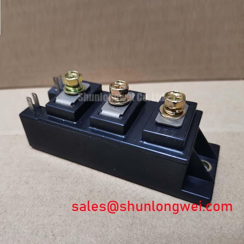
Technical Analysis: Efficiency and Thermal Management
The engineering value of the 2MBI75N-120 is centered on its electrical efficiency and thermal characteristics. The typical collector-emitter saturation voltage (VCE(sat)) of 2.2V at the nominal current of 75A directly reduces the power dissipated as heat during the on-state. This is critical in applications like motor drives, where the device spends significant time conducting current. Lower conduction losses lead to higher overall system efficiency and reduce the burden on the cooling system.
Effective thermal management is further enabled by the module’s specified thermal resistance. The junction-to-case thermal resistance (Rth(j-c)) for the IGBT is documented at 0.21°C/W per arm. This value can be compared to the diameter of a pipe; a lower number signifies a wider pipe, allowing heat to flow more easily from the active silicon chip to the module’s baseplate. This efficient heat transfer is crucial for maintaining the junction temperature within safe operating limits, directly contributing to the module’s reliability and operational lifespan, a concept further explored in our analysis of IGBT power and thermal cycling. The isolated baseplate simplifies mounting to a heatsink while ensuring the required electrical isolation of 2500V AC for one minute.
Optimized Application Scenarios
The 2MBI75N-120 is specified for applications where a balance of performance, cost, and proven reliability is paramount.
- AC Motor Controls & VFDs: In Variable Frequency Drives (VFDs), the low VCE(sat) minimizes heat generation during the motor’s run cycle, improving drive efficiency.
- Uninterruptible Power Supplies (UPS): The module’s robust RBSOA (Reverse Bias Safe Operating Area) and reliable switching characteristics are well-suited for inverter stages in UPS systems.
- Welding Power Supplies: The ability to handle pulsed collector currents up to 150A makes it a suitable candidate for the demanding, repetitive power delivery cycles found in welding equipment.
- DC Servo Drives: Provides precise and efficient control for DC servo motors, where reliability under dynamic loads is essential.
This module is an optimal match for industrial power systems operating below 50 kW where long-term durability is a primary design requirement.
Key Specification Parameters
| Absolute Maximum Ratings (Tc=25°C) | |
|---|---|
| Collector-Emitter Voltage (VCES) | 1200V |
| Gate-Emitter Voltage (VGES) | ±20V |
| Continuous Collector Current (IC) | 75A |
| Pulsed Collector Current (IC pulse) | 150A |
| Max. Power Dissipation (PC) | 600W |
| Electrical & Thermal Characteristics (Tj=25°C unless otherwise noted) | |
| Collector-Emitter Saturation Voltage (VCE(sat)) @ IC=75A, VGE=15V | 2.2V (Typ) / 2.8V (Max) |
| Gate-Emitter Threshold Voltage (VGE(th)) | 5V to 9V |
| Thermal Resistance, Junction to Case (Rth(j-c)) – IGBT | 0.21°C/W |
| Operating Junction Temperature (Tj) | -40 to +150°C |
Engineer’s FAQ
What is the recommended mounting torque for the 2MBI75N-120 and its importance?
The datasheet specifies a recommended mounting screw (M5) torque of 2.5 to 3.5 N·m. Applying the correct torque is critical for ensuring a low-resistance thermal path to the heatsink. Insufficient torque can create air gaps, increasing thermal resistance, while excessive torque can cause mechanical stress and damage the module’s isolated baseplate.
How does the Rth(j-c) value guide heatsink selection?
The junction-to-case thermal resistance (Rth(j-c)) of 0.21°C/W is a fundamental parameter for thermal calculations. An engineer uses this value, along with the calculated power dissipation, to determine the maximum allowable thermal resistance of the heatsink and thermal interface material required to keep the IGBT junction temperature below its 150°C maximum rating.
What is the significance of the Square RBSOA rating?
A Square Reverse Bias Safe Operating Area (RBSOA) indicates that the device can be turned off safely over a wide range of collector currents and voltages simultaneously. This is a key indicator of the module’s robustness and its ability to withstand stressful switching conditions, which is vital for reliable operation in hard-switched inverter topologies. For more on this topic, consider reading about IGBT avalanche ruggedness.
Does this module include an integrated NTC thermistor?
The datasheet for the 2MBI75N-120 does not indicate the presence of an integrated NTC thermistor for temperature monitoring. Systems requiring precise temperature feedback would need to implement an external sensor on or near the module’s case. Understanding the benefits of such features is covered in our discussion on the role of integrated NTCs.
Enabling Reliable Power Conversion
The 2MBI75N-120 provides a dependable building block for industrial power systems. Its design prioritizes a low on-state voltage and effective thermal dissipation, allowing engineers to develop power conversion stages that are both efficient and built for long-term service.