Fuji Electric 2MI50F-050: 500V 50A Dual IGBT Module for High-Efficiency Industrial Power Conversion
Fuji Electric 2MI50F-050 Dual IGBT Module | 500V 50A
Engineering Excellence in Fast-Switching Dual IGBT Topologies
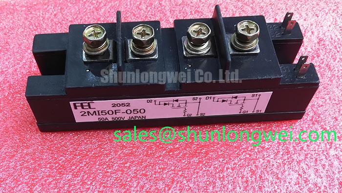
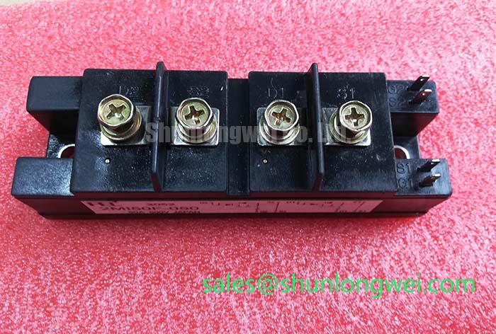
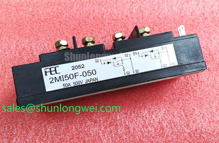
The 2MI50F-050 is a high-performance 2-in-1 IGBT module engineered by Fuji Electric to meet the rigorous demands of medium-power industrial switching. Utilizing a dual-configuration package, this module integrates two Insulated Gate Bipolar Transistors specified for high-speed operation and low drive power. It serves as a cornerstone for designers requiring high reliability in compact form factors, particularly where efficient thermal dissipation and minimal parasitic inductance are prioritized. For engineers asking how to optimize high-frequency PWM performance, the 2MI50F-050 provides a balanced solution between low saturation voltage and rapid turn-off characteristics.
- Core Specifications: 500V | 50A | 200W Total Power Dissipation
- Key Advantages: Optimized for high-speed switching environments and features a low-inductance module structure to suppress voltage transients.
Download Official Datasheet (PDF)
Technical Analysis: Efficiency and Thermal Management
The technical architecture of the 2MI50F-050 centers on its ability to minimize conduction and switching losses simultaneously. The Collector-Emitter Saturation Voltage ($V_{CE(sat)}$), typically rated at a competitive level for its generation, ensures that the device maintains high efficiency during the “on” state. By reducing the energy lost as heat during conduction, engineers can decrease the physical size of the required cooling system. This is particularly critical in high-density power semiconductors assemblies where airflow may be restricted.
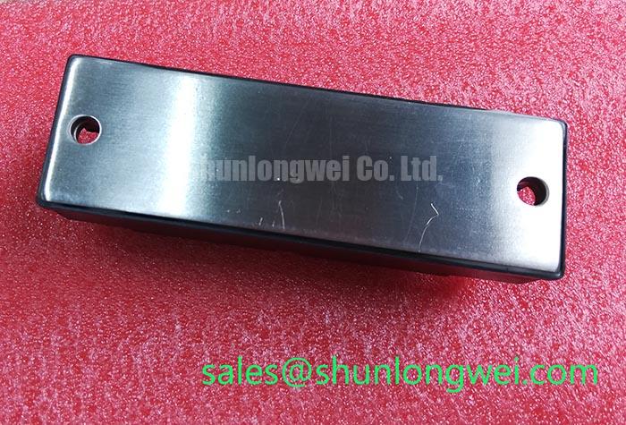
One of the most critical parameters for long-term reliability is the Junction-to-Case Thermal Resistance ($R_{th(j-c)}$). Analogy: Think of this thermal resistance as the diameter of a drainage pipe; a lower value means heat can flow out of the silicon die more freely, preventing the “clogging” of energy that leads to thermal runaway. For the 2MI50F-050, the thermal design is optimized to maintain a stable junction temperature even under continuous 50A loads. Proper thermal design and Zth curve analysis are essential to ensure the device remains within its Safe Operating Area (SOA).
Optimized Application Scenarios
The electrical characteristics of the 2MI50F-050 make it an ideal candidate for several demanding industrial roles:
- High-Frequency Inverters: The fast-switching capability reduces $E_{off}$ losses, enabling higher carrier frequencies in DC-to-AC conversion.
- Uninterruptible Power Supplies (UPS): High reliability and tight parameter distribution across the dual-unit package ensure stable power delivery during critical transitions.
- Welding Machines: The 500V rating provides a robust buffer for the voltage spikes commonly encountered in arc welding power stages.
- DC Choppers: Its dual configuration allows for simplified half-bridge implementation in motor drive braking or voltage regulation circuits.
Best Match: Systems requiring 500V blocking capability with 50A continuous current and high-speed PWM control up to 20kHz.
Key Specifications Table
| Category | Parameter | Typical Value |
|---|---|---|
| Absolute Maximum Ratings | Collector-Emitter Voltage ($V_{CES}$) | 500V |
| Continuous Collector Current ($I_C$) | 50A | |
| Collector Power Dissipation ($P_C$) | 200W | |
| Electrical Characteristics | Collector-Emitter Saturation Voltage | Refer to Datasheet |
| Gate-Emitter Threshold Voltage | 3.0V to 6.0V | |
| Thermal Features | Junction Operating Temperature | Max +150°C |
Engineer’s FAQ
1. What are the primary considerations for calculating the heat sink for the 2MI50F-050?
Engineers must sum the switching losses ($P_{sw}$) and conduction losses ($P_{cond}$) based on the application’s frequency and duty cycle. Using the junction-to-case thermal resistance ($R_{th(j-c)}$) and the interface thermal resistance of the thermal paste, ensure the junction temperature ($T_j$) does not exceed 150°C under worst-case ambient conditions.
2. Does the 2MI50F-050 require a negative gate drive voltage?
While the module can be driven with a 0V to +15V signal, a negative bias (e.g., -5V) during the “off” state is recommended in high $dv/dt$ environments to prevent parasitic turn-on. Understanding IGBT latch-up and parasitic turn-on is vital for robust driver design.
3. Can this module be used in a standard H-Bridge configuration?
Yes, since the 2MI50F-050 is a 2-in-1 (dual) module, two such modules can be combined to form a full H-Bridge for single-phase inverter or DC motor reversal applications. Its integrated nature helps in preventing common IGBT failure modes related to layout-induced oscillations.
The Designer’s Choice for Stable Power Conversion
The 2MI50F-050 represents a refined balance of power density and switching agility. By adhering strictly to the data provided in the Fuji Electric documentation, engineers can leverage this module’s predictable electrical behavior to achieve high efficiency in industrial inverter and converter designs. Its dual-topography package not only saves board space but simplifies the mechanical integration of high-reliability power systems, ensuring that your design meets both performance and longevity targets.