FZ2400R17KE3_S1: Technical Analysis of a High-Power IGBT for Megawatt Systems
FZ2400R17KE3_S1: 1700V 2400A High-Power IGBT Module
Introduction and Core Highlights
The Infineon FZ2400R17KE3_S1 is a high-power IGBT module engineered for megawatt-class inverter and converter systems, delivering exceptional current handling with optimized conduction performance. Based on Infineon’s TrenchSTOP™ IGBT3 technology, this module provides a robust solution for high-power applications by balancing low on-state voltage with moderate switching frequencies. Its low VCE(sat) is a key factor in managing the thermal load inherent in such high-current applications, simplifying heatsink requirements.
- Core Specifications: 1700V | 2400A (Nominal) | VCE(sat) 1.70V (typ.)
- Key Advantages: Enables high power density in large-scale converters and reduces system cooling requirements through low conduction losses.
Download the Official FZ2400R17KE3_S1 Datasheet (PDF)
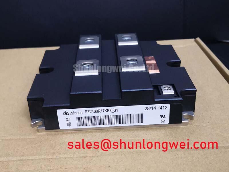
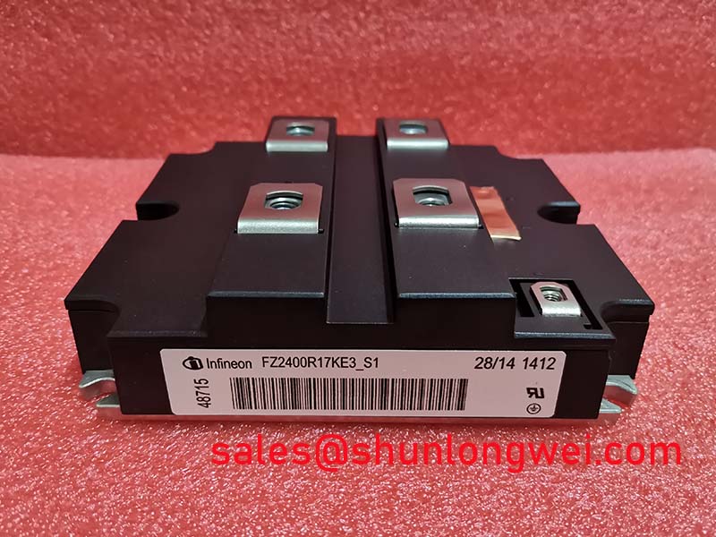
Technical Analysis for High-Power Systems
The standout characteristic of the FZ2400R17KE3_S1 is its massive nominal collector current (IC nom) of 2400A. This high current capacity allows designers to build multi-megawatt systems with fewer parallel-connected modules. Reducing the module count simplifies the overall mechanical construction, reduces the complexity of gate driver circuitry, and minimizes potential current-sharing imbalances that can occur when paralleling multiple IGBTs. The robust IHM-B housing is specifically constructed to manage the electrical and thermal stresses associated with such high currents, ensuring reliable connections and effective heat transfer.
A low collector-emitter saturation voltage (VCE(sat)) is critical for efficiency in high-current devices. The FZ2400R17KE3_S1 specifies a typical VCE(sat) of just 1.70V at its nominal current of 2400A (at Tvj=125°C). This parameter is analogous to friction for the electrical current; a lower value means less energy is converted into waste heat during operation. For a system designer, this directly translates into lower conduction losses and, subsequently, a reduced thermal burden on the cooling system. This efficiency is central to achieving a reliable thermal management strategy for the entire power converter.
Optimized Application Scenarios
The specifications of this module are tailored for very specific, high-demand applications:
- Wind Turbine Converters: The 1700V blocking voltage is well-suited for medium-voltage grid interfaces, while the 2400A current rating enables the control of multi-megawatt turbines.
- Industrial High-Power Drives: Ideal for variable frequency drives (VFDs) controlling very large motors in applications such as marine propulsion, mining excavators, and industrial mills where immense torque and power are required.
- Large-Scale Solar Inverters: Its high current capability allows for the design of central inverters with higher power ratings, consolidating the output of large photovoltaic arrays and reducing overall system complexity.
- Medium-Voltage Soft Starters: Provides the robust control needed to manage high inrush currents when starting large AC motors.
This module is best matched for systems where maximizing power throughput per device is the primary architectural driver, simplifying high-power inverter design.
Key Specification Parameters
| Key Parameters for FZ2400R17KE3_S1 | |
|---|---|
| Absolute Maximum Ratings | Value |
| Collector-Emitter Voltage (V_CES) | 1700 V |
| Continuous DC Collector Current (I_C) | 2400 A (Tc = 80°C) |
| Repetitive Peak Collector Current (I_CRM) | 4800 A (tP = 1 ms) |
| Gate-Emitter Voltage (V_GES) | ±20 V |
| Operating Junction Temperature (T_vj op) | -40 to +150 °C |
| Electrical & Thermal Characteristics | Value (Typical) |
| Collector-Emitter Saturation Voltage (V_CEsat) | 1.70 V (at I_C=2400A, T_vj=125°C) |
| Gate Threshold Voltage (V_GE(th)) | 5.8 V |
| Turn-On Energy (E_on) | 4000 mJ |
| Turn-Off Energy (E_off) | 6300 mJ |
| Thermal Resistance, Junction-to-Case (R_thJC) | 6 K/kW (per switch) |
Note: All data is sourced from the official Infineon FZ2400R17KE3_S1 datasheet. Refer to the document for complete characteristic curves and test conditions.
Engineer FAQ
- What are the key thermal design considerations for the FZ2400R17KE3_S1?
- The primary challenge is dissipating heat from high conduction and switching losses. The datasheet specifies a low junction-to-case thermal resistance of 6 K/kW per switch. Effective thermal design requires a high-performance heatsink, proper application of thermal interface material, and securing the module with the recommended mounting torque of 10 Nm (±15%) to ensure minimal contact resistance.
- How does the IHM-B housing affect installation?
- The IHM-B (IGBT High-Power Module) housing features large, flat power terminals designed for robust, low-inductance busbar connections. This is critical for managing the high currents and minimizing voltage overshoot during switching. Designers must ensure the busbar system is engineered for a secure, flush fit to these terminals to achieve reliable performance. A guide on the impact of parasitic inductance provides further context.
- What is the intended switching frequency for this module?
- This module uses Infineon’s TrenchSTOP™ IGBT3 technology, which is optimized for low conduction losses (VCEsat) rather than ultra-high-speed switching. The datasheet shows switching energies (Eon/Eoff) of 4000 mJ and 6300 mJ respectively. This suggests it is best suited for applications operating in the lower kilohertz range, typical for high-power industrial drives and grid-tied converters.
- Can this module be used in parallel?
- Yes, the datasheet indicates it is suitable for parallel operation. The positive temperature coefficient of VCE(sat) aids in balancing current between parallel-connected modules. However, achieving successful paralleling requires careful attention to symmetrical layout for both electrical busbars and thermal management to ensure even load and heat distribution.
Enabling Megawatt-Scale Power Conversion
The FZ2400R17KE3_S1 offers the foundational current capacity and thermal efficiency necessary to engineer robust and power-dense converters. Its specifications directly support the goals of system simplification and improved performance in the most demanding power semiconductor applications, from renewable energy to heavy industry.