Hitachi PM45502C: A Technical Review of a High-Gain Power Module
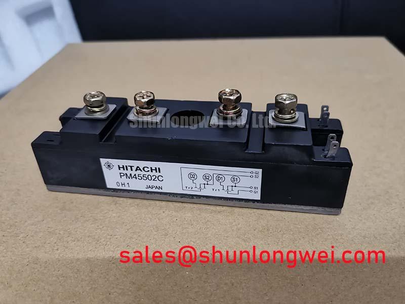
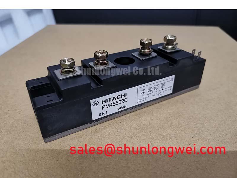
Hitachi PM45502C 450V 50A Power Transistor Module
Introduction and Core Highlights
The Hitachi PM45502C is a power Darlington transistor module engineered for robust performance in low to medium-frequency power control applications. Its defining characteristic is a high DC current gain (hFE), which allows a small base current to control a substantial load, simplifying the requirements and cost of drive circuitry. This module provides a direct and reliable solution for managing significant power with minimal external components.
- Core Specifications: 450V | 50A | hFE 750 (typ)
- Key Advantages: Simplifies drive circuit design, robust thermal management due to isolated package.
- Design Consideration: The high gain significantly reduces the base current needed, allowing for control from lower-power driver stages.
Download Official Datasheet (PDF)
Technical Analysis of Core Features
The most significant engineering advantage of the PM45502C is its high DC current gain (hFE), specified with a typical value of 750 at a collector current of 50A. This high gain means that a relatively small input current to the base terminal can effectively switch the full 50A load. For system designers, this translates directly into a less complex and lower-power drive circuit. It eliminates the need for multi-stage amplification often required to drive lower-gain transistors, reducing component count, PCB space, and overall system cost.
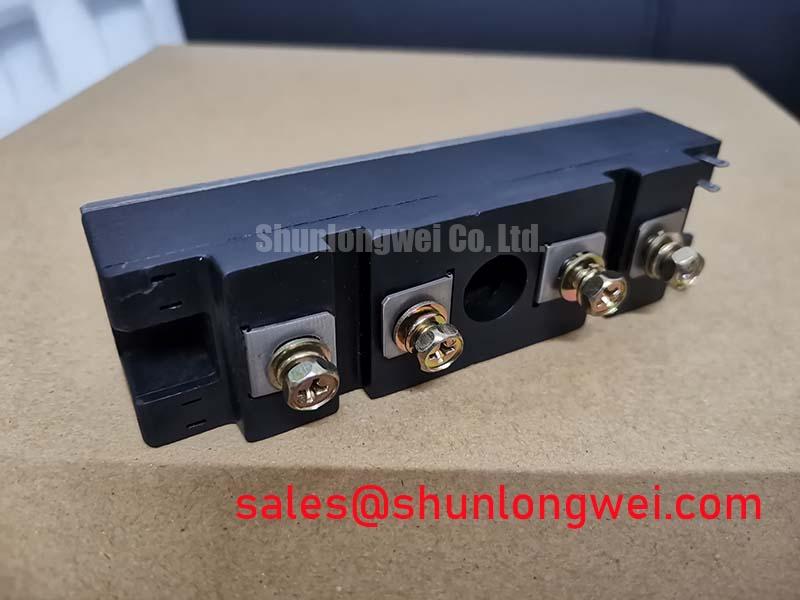
Effective thermal dissipation is critical for reliability in power applications. The PM45502C addresses this with a low thermal resistance from junction to case (Rth(j-c)) of 0.6 °C/W. This parameter can be compared to the width of a pipe for heat flow; a lower value indicates a wider pipe, allowing heat to escape the semiconductor junction more easily. This efficient heat transfer, combined with the module’s isolated baseplate (Viso of 2500V AC), enables straightforward and secure mounting to a heatsink, ensuring the junction temperature remains within its safe operating limits of 150°C. For further reading, see this guide on mastering thermal design.
Optimized Application Scenarios
The characteristics of the PM45502C make it well-suited for several specific industrial applications:
- DC Motor Controllers: Its ability to handle 50A of continuous current makes it ideal for driving medium-sized DC motors where precise, high-frequency switching is not the primary requirement.
- Low-Frequency Inverters and Converters: The robust nature and high current capability are beneficial in power conversion systems operating below 20 kHz.
- High-Power Solenoid and Relay Drivers: The high hFE allows the module to be driven directly from logic-level outputs with minimal buffering, simplifying control of large industrial solenoids.
- Linear Regulated Power Supplies: It can function as a high-current pass element, offering a durable solution for high-power linear regulation tasks.
This module is best matched for cost-sensitive industrial power control systems where simplified drive logic and robust current handling are the primary engineering goals.
Key Specification Parameters
| Absolute Maximum Ratings (at Tc=25°C) | |
|---|---|
| Collector-Base Voltage (VCBO) | 450V |
| Collector-Emitter Voltage (VCEO) | 450V |
| Emitter-Base Voltage (VEBO) | 7V |
| Collector Current (IC) | 50A |
| Base Current (IB) | 2A |
| Collector Power Dissipation (Pc) | 208W |
| Electrical Characteristics | |
| Collector-Emitter Saturation Voltage (VCE(sat)) | 2.0V max (at IC=50A, IB=0.2A) |
| DC Current Gain (hFE) | 750 typ (at IC=50A, VCE=5V) |
| Turn-On Time (ton) | 2.5 µs typ |
| Turn-Off Time (toff) | 10 µs typ |
| Isolation Voltage (Viso) | 2500V (AC, 1 minute) |
| Thermal Characteristics | |
| Thermal Resistance (Rth(j-c)) | 0.6 °C/W max |
Engineer’s FAQ
- What are the base drive requirements for the PM45502C?
- Based on its typical hFE of 750 at 50A, the required base current (IB) is approximately 67mA (50A / 750). The datasheet specifies test conditions with an IB of 0.2A to ensure saturation. This low drive current requirement simplifies the driver stage, often allowing for direct control from a simple driver IC or a small transistor stage, reducing overall design complexity.
- How do I determine the appropriate heatsink for this module?
- To select a heatsink, first calculate the total power dissipation (P_loss), primarily from conduction loss (VCE(sat) * IC). Then, use the thermal resistance values in the formula: ΔT = P_loss * (Rth(j-c) + Rth(c-s) + Rth(s-a)), where Rth(c-s) is the case-to-sink thermal resistance (thermal interface material) and Rth(s-a) is the sink-to-ambient thermal resistance. The PM45502C datasheet provides the critical Rth(j-c) of 0.6 °C/W, which is the starting point for this calculation.
- Is the PM45502C suitable for high-frequency switch-mode power supplies (SMPS)?
- No, this module is not recommended for high-frequency designs. The datasheet specifies typical turn-on and turn-off times of 2.5µs and 10µs, respectively. These relatively slow switching speeds would lead to excessive switching losses at frequencies above a few kilohertz, reducing efficiency and creating significant thermal challenges. It is best utilized in DC or low-frequency switching applications. Exploring modern options might be necessary for such cases, such as understanding the difference between SiC vs IGBT.
Concluding Remarks
The Hitachi PM45502C power transistor module delivers a practical and effective solution for medium-power applications. By integrating a high-gain Darlington pair into a thermally efficient and electrically isolated package, it enables engineers to implement robust power control with simplified drive circuitry. This focus on straightforward application and reliable performance makes it a valuable component for a wide range of industrial control systems.