Infineon FF1000R17IE4: High-Performance 1700V 1000A TRENCHSTOP™ IGBT4 Power Module Overview
FF1000R17IE4 Infineon TRENCHSTOP™ IGBT4 Power Module Description
The FF1000R17IE4 is a high-performance, dual-channel IGBT module engineered for megawatt-scale power conversion systems where high current density and exceptional reliability are non-negotiable. Utilizing Infineon’s established TRENCHSTOP™ IGBT4 technology, this module is optimized to provide a robust solution for demanding switching environments, balancing low conduction losses with superior short-circuit ruggedness. Designed within the industry-standard PrimePACK™ 3 housing, the FF1000R17IE4 enables engineers to maximize power density while maintaining stringent thermal management standards.
- Core Specifications: 1700V | 1000A | VCE(sat) 1.95V (typical at 125°C)
- Key Advantages: Enhanced thermal cycling capability and simplified gate drive design through optimized switching characteristics.
- Design Integration: Includes an integrated NTC thermistor, providing real-time temperature telemetry to safeguard against over-temperature conditions in high-stress industrial applications.
Download Official Datasheet (PDF)
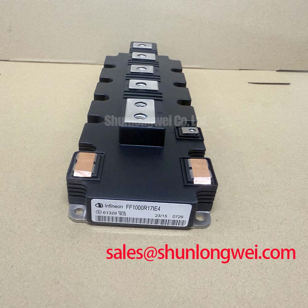

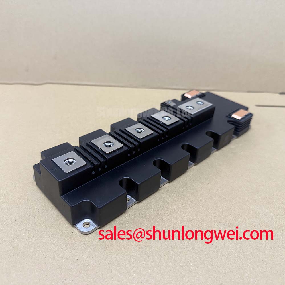
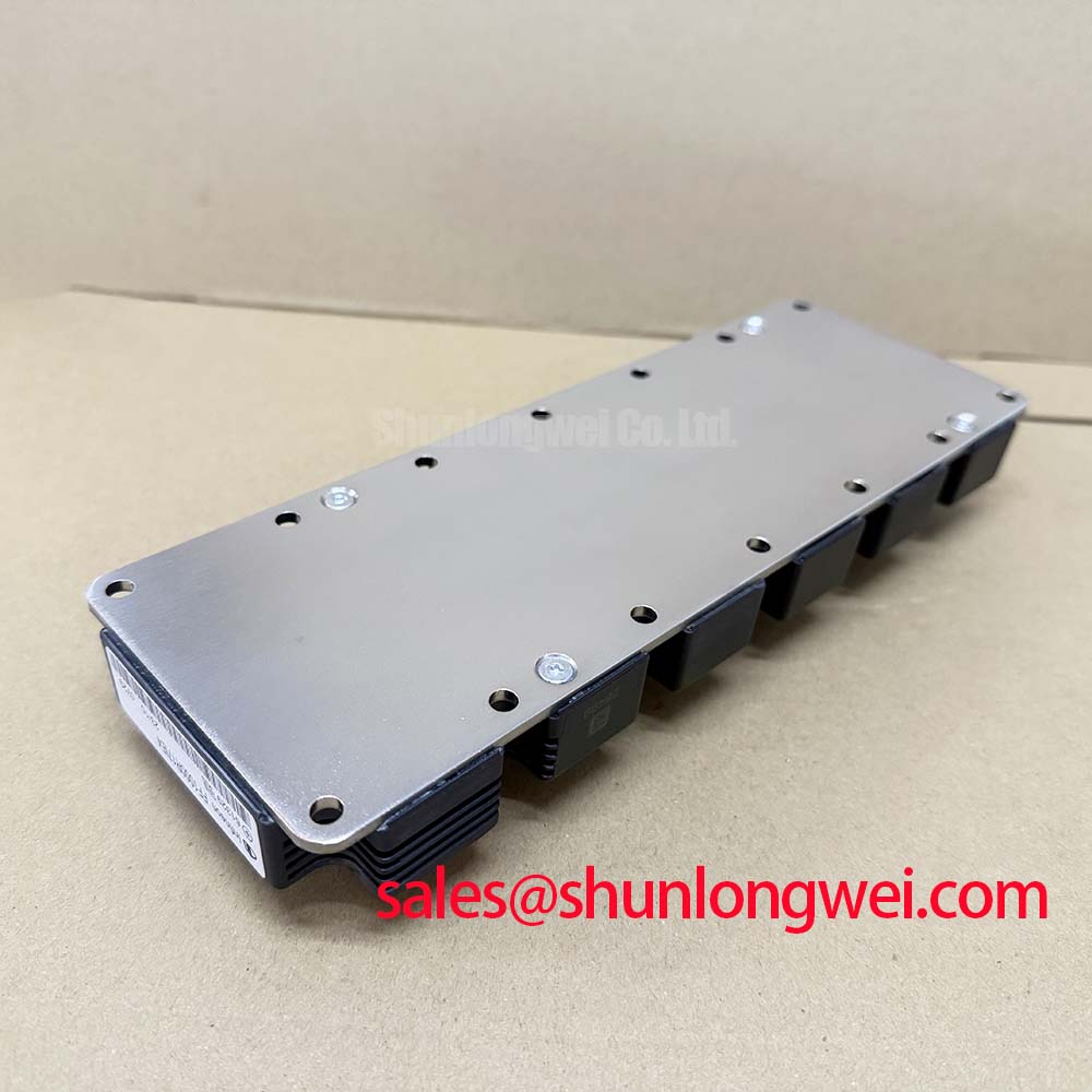
Technical Analysis of the TRENCHSTOP™ IGBT4 Architecture
The technical sophistication of the FF1000R17IE4 lies in its trench gate evolution, which significantly reduces the saturation voltage ($V_{CE(sat)}$). For industrial power electronics, $V_{CE(sat)}$ is the primary determinant of conduction loss. In the FF1000R17IE4, a typical value of 1.95V at $T_{vj} = 125°C$ ensures that thermal dissipation remains manageable even at continuous 1000A loads. This technical efficiency directly supports the module’s Unique Value Proposition (UVP) of high power density without compromising the device’s lifecycle under heavy thermal cycling.
Thermal resistance is another critical parameter defined in the official documentation. The module features an extremely low thermal resistance junction-to-case ($R_{thJC}$) for the IGBT of 0.024 K/W. To understand this in an engineering context, one can think of thermal resistance as the width of a drainage pipe; a lower resistance (a wider pipe) allows heat (the water) to flow away from the junction much more efficiently, preventing the semiconductor die from reaching critical failure temperatures. This efficiency is further bolstered by isolated baseplates, which provide the electrical isolation necessary for direct mounting on liquid-cooled or high-performance air-cooled heatsinks.
Furthermore, the FF1000R17IE4 is designed with high short-circuit withstand time of $10mu s$ at $150°C$. This duration gives system protection controllers sufficient time to react to fault conditions, such as phase-to-ground or phase-to-phase shorts, inherently increasing the survivability of the entire power stack in high voltage IGBT applications.
Optimized Application Scenarios
The technical parameters of the FF1000R17IE4 make it suitable for several high-capacity infrastructure roles:
- Wind Turbines: High short-circuit robustness and 1700V rating provide the necessary headroom for grid-fault ride-through (LVRT) compliance.
- Megawatt Solar Inverters: The low-loss E4 chip version maximizes energy harvest efficiency in central inverter architectures.
- Heavy Industrial Drives: Superior power cycling capability supports the frequent load variations inherent in mining and large-scale manufacturing motor control.
- Traction Converters: The robust PrimePACK™ 3 housing is designed to withstand the mechanical and thermal stresses of railway environments.
Best Match: Megawatt-scale renewable energy converters and heavy-duty industrial drives requiring 1700V isolation and maximized current density per square inch.
Key Specifications Table
| Parameter Category | Specific Parameter | Value (Typical/Max) |
|---|---|---|
| Absolute Maximums | Collector-Emitter Voltage ($V_{CES}$) | 1700 V |
| Continuous DC Collector Current ($I_{C,nom}$) | 1000 A | |
| Repetitive Peak Collector Current ($I_{CRM}$) | 2000 A | |
| Electrical Characteristics | IGBT Saturation Voltage ($V_{CE,sat}$ @ 125°C) | 1.95 V |
| Gate Threshold Voltage ($V_{GE,th}$) | 5.2 V (min) to 6.4 V (max) | |
| Thermal & Mechanical | Thermal Resistance ($R_{thJC}$, per IGBT) | 0.024 K/W |
| Operating Junction Temperature ($T_{vj,op}$) | -40°C to 150°C |
Engineer FAQ
Q1: How should I calculate the cooling requirements for the FF1000R17IE4?
A1: Cooling design should be based on the total power dissipation ($P_{tot}$), which is 6.25 kW per IGBT at a case temperature of 25°C. For practical designs, use the $R_{thJC}$ (0.024 K/W) combined with your chosen heatsink’s thermal resistance ($R_{thCH}$) to ensure junction temperatures do not exceed the $150°C$ operational limit under peak load.
Q2: What is the benefit of the integrated NTC thermistor in this specific module?
A2: The NTC thermistor provides a resistance value that changes with the module’s internal temperature. By integrating this into the gate driver’s logic, engineers can implement active thermal derating or emergency shutdown, significantly reducing the risk of catastrophic failure due to cooling pump failure or ventilation blockage.
Q3: Are there specific mounting considerations for the PrimePACK™ 3 housing?
A3: Yes. The datasheet specifies precise mounting torques for both the baseplate (3 Nm to 6 Nm) and the power terminals (8 Nm to 10 Nm). Consistent pressure is vital to minimize contact thermal resistance and prevent mechanical stress on the internal ceramic substrates.
The Infineon FF1000R17IE4 stands as a definitive component for high-power switching, offering a technical synergy between the TRENCHSTOP™ IGBT4 silicon and the thermally efficient PrimePACK™ 3 enclosure. By providing a reliable 1000A capacity and a comprehensive protection suite via the integrated NTC, it empowers engineers to build more compact, efficient, and resilient megawatt-scale power systems.