Infineon FF100R17IE4 IGBT Module: A Technical Analysis for High-Power Designs
Infineon FF100R17IE4 1700V 100A IGBT Module Datasheet
Introduction and Core Highlights
The Infineon FF100R17IE4 is a high-voltage IGBT module engineered for demanding power conversion applications. This module integrates TRENCHSTOP™ IGBT3 and Emitter Controlled 3 diode technology, establishing a benchmark for efficiency and reliability. It delivers a robust performance profile by balancing low conduction losses with substantial short-circuit ruggedness. A key engineering advantage is the positive temperature coefficient of its saturation voltage, which intrinsically simplifies the process of paralleling modules for higher power output.
- Core Specifications: 1700V | 100A | VCE(sat) (typ) 2.15V
- Key Advantages: Low conduction and switching losses, simplified parallel operation for scalability.
Download the Official FF100R17IE4 Datasheet (PDF)


Technical Analysis for System Design
The engineering value of the FF100R17IE4 is rooted in its core semiconductor technology. The TRENCHSTOP™ IGBT3 provides a low collector-emitter saturation voltage (VCE(sat)) of 2.15V at nominal current (100A, 25°C). This parameter directly correlates to reduced conduction losses, which is a primary source of heat generation. You can think of VCE(sat) as the electrical “friction” the device exhibits when it’s on; a lower value means less energy is wasted as heat, leading to higher system efficiency and potentially smaller heatsinks.
A significant feature for high-power system designers is the positive temperature coefficient of VCE(sat). As an individual module’s temperature increases under load, its on-state voltage also rises slightly. This characteristic creates a natural self-balancing effect when multiple IGBT modules are connected in parallel. The warmer, more resistive module automatically cedes current to its cooler neighbors, ensuring even load distribution and preventing thermal runaway without requiring complex external measurement and control circuits.
System reliability is further enhanced by a short-circuit withstand time (tsc) of 10 microseconds. This provides a critical window for the system’s protection circuitry to detect a fault condition and safely shut down the drive. This level of robustness is essential in industrial environments where unexpected load conditions can occur.

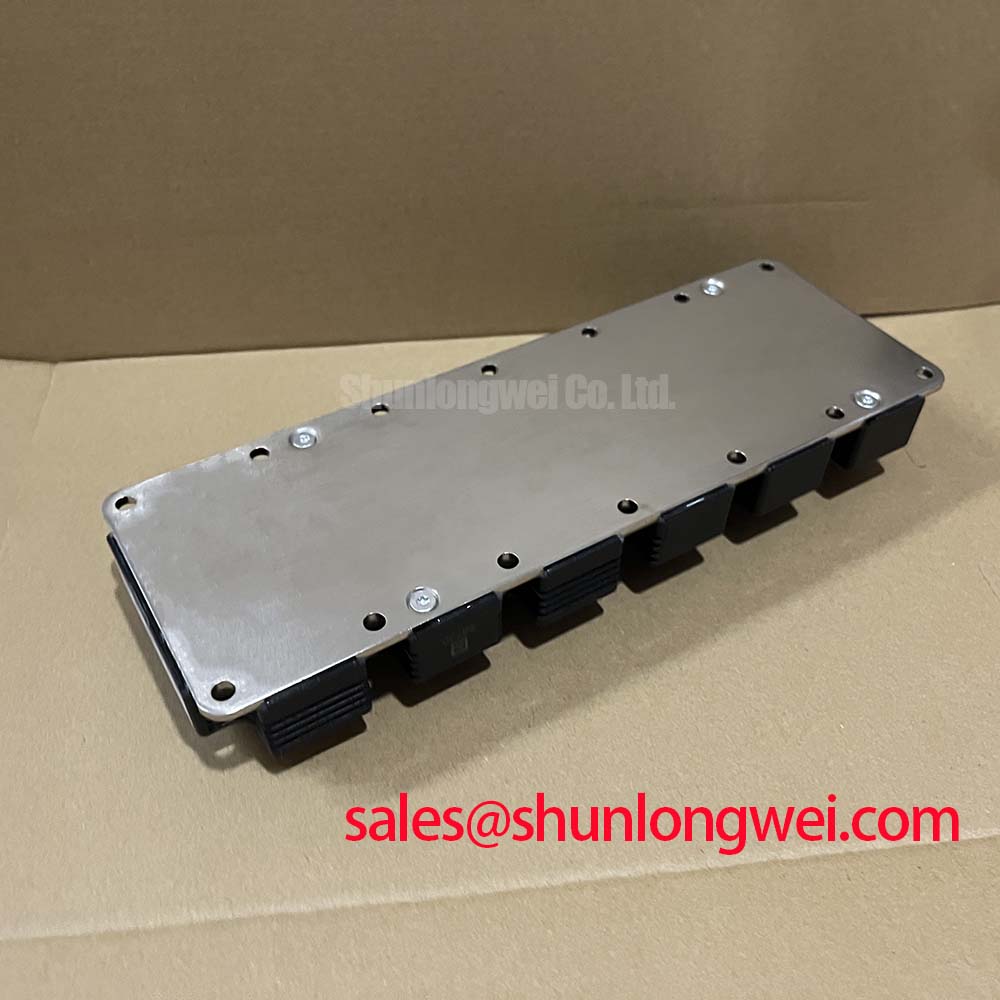

Optimized Application Scenarios
The FF100R17IE4 module’s specifications make it a strong candidate for several high-voltage applications:
- Industrial Motor Drives: The 1700V rating provides a substantial safety margin for inverters operating on high DC bus voltages, while the robust short-circuit withstand capability protects against motor winding faults.
- Solar Inverters: In utility-scale solar installations, high efficiency is paramount. The module’s low VCE(sat) minimizes power loss, maximizing the energy delivered to the grid.
- Uninterruptible Power Supplies (UPS): System uptime is critical. The module’s proven reliability and features that support robust gate drive design contribute to a dependable power backup system.
- Welding Power Supplies: The ability to handle high currents and withstand short-circuit events makes it suitable for the demanding, cyclical loads found in industrial welding equipment.
This module is an optimal choice for power conversion systems where efficiency, high-voltage operation, and reliable paralleling are primary design considerations.
Key Specifications of the FF100R17IE4
| Absolute Maximum Ratings (at Tvj = 25°C unless otherwise specified) | ||
|---|---|---|
| Parameter | Symbol | Value |
| Collector-Emitter Voltage | VCES | 1700 V |
| Continuous DC Collector Current (TC=80°C) | IC,nom | 100 A |
| Repetitive Peak Collector Current (tp=1ms) | ICRM | 200 A |
| Gate-Emitter Peak Voltage | VGES | ±20 V |
| Short Circuit Withstand Time (VGE ≤ 15V, VCC = 1000V, Tvj ≤ 150°C) | tsc | 10 µs |
| Thermal and Electrical Characteristics | ||
| Collector-Emitter Saturation Voltage (IC=100A, VGE=15V, Tvj=25°C) | VCE(sat) | 2.15 V (typ.) |
| Gate Threshold Voltage (IC=4.0mA, VCE=VGE, Tvj=25°C) | VGE(th) | 5.8 V (typ.) |
| Thermal Resistance, Junction-to-Case (per IGBT) | RthJC | 0.24 K/W (max) |
| Thermal Resistance, Case-to-Heatsink (per module) | RthCH | 0.075 K/W (typ.) |
| Maximum Junction Temperature | Tvj max | 150°C |
Engineer’s FAQ for the FF100R17IE4
1. What makes the FF100R17IE4 suitable for parallel connection?
The module is well-suited for paralleling due to its VCE(sat) having a positive temperature coefficient. This creates a natural current-sharing mechanism among parallel modules, preventing one device from disproportionately carrying the load, which enhances the reliability of the overall high-power array.
2. How do I approach the thermal design for this module?
Effective thermal management starts with the datasheet’s thermal resistance values. Calculate total power loss (conduction + switching). The required heatsink thermal resistance (RthSA) can be estimated by: RthSA < (Tvj,max - Ta) / P_loss - RthJC - RthCH. Ensure the calculated heatsink keeps the junction temperature below the 150°C maximum under worst-case operating conditions.
3. What are the recommended gate drive parameters?
The datasheet specifies a maximum gate-emitter voltage (VGES) of ±20V. For optimal performance, a +15V turn-on voltage and a negative turn-off voltage (e.g., -8V to -15V) are recommended. The negative voltage ensures a robust off-state, especially in noisy environments. Gate resistor (RGon, RGoff) values, detailed in the datasheet, should be selected to balance switching speed, losses, and EMI performance.
4. What is the purpose of the integrated NTC thermistor?
The built-in NTC thermistor provides a means for real-time temperature monitoring of the module’s baseplate. This feedback is critical for implementing over-temperature protection in the control system, serving as a vital safety feature to prevent the module from exceeding its maximum operating temperature.
Enabling Robust High-Voltage Designs
For engineers tasked with creating reliable and efficient high-power converters, the Infineon FF100R17IE4 offers a well-documented and robust component solution. The combination of TRENCHSTOP™ IGBT3 technology and design features that simplify both power semiconductor scaling and thermal design provides a dependable path to achieving system-level performance goals in a standard industrial package.