Infineon FF150R12KE3G 1200V 150A IGBT Module: A Technical Review and Application Guide
Infineon FF150R12KE3G 1200V 150A IGBT Module Datasheet
Technical Introduction to the FF150R12KE3G IGBT Module
The Infineon FF150R12KE3G is a 1200V, 150A half-bridge IGBT module that leverages TRENCHSTOP™ IGBT3 technology to deliver a balanced performance profile for industrial power conversion systems. This module integrates two IGBTs with anti-parallel Emitter Controlled diodes in a standard 62mm EconoPACK™ 3 package, providing a robust solution that emphasizes low conduction and switching losses. This combination enables higher system efficiency and reliable thermal management, making it a foundational component for demanding applications.
- Core Specifications: 1200V | 150A | VCE(sat) (typ.) 1.70V
- Key Advantages: Low conduction losses reduce operating temperatures. Optimized for switching frequencies found in industrial converters.
For systems where efficiency and thermal stability are primary design goals, the FF150R12KE3G provides a well-documented and field-proven platform.
Download the Official FF150R12KE3G Datasheet (PDF)
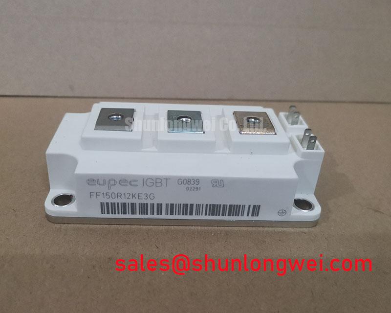

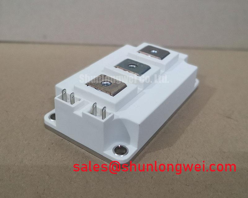

Technical Analysis: Efficiency and Thermal Performance
The engineering value of the FF150R12KE3G is rooted in its TRENCHSTOP™ IGBT3 chip technology. A critical parameter is its low collector-emitter saturation voltage (VCE(sat)), which is a typical 1.70V at nominal current and 25°C. This value is a direct indicator of conduction losses. Think of VCE(sat) as the friction inside a pipe; a lower value means less energy is converted into waste heat as current flows through the device. This reduction in heat generation simplifies the thermal design, potentially allowing for smaller heatsinks and contributing to a more compact and cost-effective system. For a deeper understanding of thermal design, explore this practical guide to the Zth curve.
Furthermore, the module is specified for an operating junction temperature (Tvj op) up to 150°C, providing significant headroom for industrial applications that may experience demanding thermal cycles. The module’s thermal resistance from junction to case (RthJC) is 0.13 K/W for the IGBT. This low thermal resistance ensures that the heat generated during operation can be efficiently transferred away from the semiconductor junction to the heatsink. Effective heat dissipation is fundamental to preventing device degradation and ensuring long-term operational reliability, a topic further explored in our analysis of IGBT failure modes.
Optimized Application Scenarios
The FF150R12KE3G is engineered for specific power conversion tasks where efficiency and reliability are paramount.
- Industrial Motor Drives: Its low VCE(sat) and optimized switching characteristics are well-suited for variable frequency drives (VFDs), minimizing power loss and improving motor control accuracy.
- Solar Inverters: The module’s efficiency helps maximize the energy harvested from photovoltaic arrays by reducing the power consumed during the DC-to-AC conversion process.
- Uninterruptible Power Supplies (UPS): The robust thermal performance and proven reliability of the EconoPACK™ package make it a dependable choice for critical backup power systems.
- Welding Equipment: The module’s ability to handle repetitive peak currents (ICRM of 300A) makes it suitable for the pulsed power demands of modern welding power supplies.
This module is best matched for systems operating at moderate switching frequencies where balancing conduction and switching losses is key to overall efficiency.
Key Specifications of the FF150R12KE3G
| Absolute Maximum Ratings (Tvj = 25°C unless otherwise specified) | ||
|---|---|---|
| Collector-Emitter Voltage (VCES) | 1200 V | |
| Continuous DC Collector Current (IC) | 150 A | TC = 80°C, Tvj max = 150°C |
| Repetitive Peak Collector Current (ICRM) | 300 A | tP = 1 ms |
| Gate-Emitter Peak Voltage (VGES) | ±20 V | |
| Total Power Dissipation (Ptot) | 780 W | TC = 25°C, Tvj max = 150°C |
| Electrical Characteristics | ||
| Collector-Emitter Saturation Voltage (VCE(sat)) | 1.70 V (typ) / 2.15 V (max) | IC = 150 A, VGE = 15 V, Tvj = 25°C |
| Gate Threshold Voltage (VGE(th)) | 5.0 V (min) / 5.8 V (typ) / 6.5 V (max) | IC = 6.00 mA, VCE = VGE, Tvj = 25°C |
| Turn-on Energy (Eon) | 17.0 mJ (typ) | IC = 150 A, VCE = 600 V, Tvj = 125°C |
| Turn-off Energy (Eoff) | 21.0 mJ (typ) | IC = 150 A, VCE = 600 V, Tvj = 125°C |
| Thermal & Mechanical Specifications | ||
| Operating Junction Temperature (Tvj op) | -40 to 150 °C | |
| Thermal Resistance, Junction-to-Case (RthJC) | 0.13 K/W (per IGBT) | |
| Thermal Resistance, Case-to-Heatsink (RthCH) | 0.030 K/W (per module) | With thermal grease |
| Isolation Test Voltage (VISOL) | 2.5 kV | RMS, f = 50 Hz, t = 1 min |
Engineer’s FAQ for the FF150R12KE3G
1. What are the main thermal design considerations for this 1200V 150A IGBT?
The primary goal is to keep the junction temperature below the 150°C maximum. Start with the total power loss, calculated from conduction and switching losses under your operating conditions. Use the RthJC (0.13 K/W) and RthCH (0.030 K/W) values to determine the required heatsink-to-ambient thermal resistance. Ensure proper mounting torque (3.0 – 6.0 Nm) and the use of a suitable thermal interface material to achieve the specified RthCH.
2. How does the TRENCHSTOP™ IGBT3 technology benefit a motor drive application?
This technology provides a favorable trade-off between conduction losses (low VCE(sat)) and switching losses (moderate Eon/Eoff). For motor drives, which often operate at switching frequencies between 4 kHz and 16 kHz, this balance results in high overall efficiency and reduced heat generation compared to older IGBT technologies. For more on the evolution of this technology, read about modern IGBT architectures.
3. Can the FF150R12KE3G be used in parallel to achieve higher current ratings?
Yes, paralleling is possible but requires careful design. The positive temperature coefficient of VCE(sat) helps balance current sharing between modules as they heat up. However, it is critical to ensure a symmetrical busbar layout to minimize stray inductance and use a common gate driver with individual gate resistors to prevent oscillations. An unbalanced layout can lead to unequal current distribution and potential module failure. Learn more about robust gate drive design for such scenarios.
4. What is the significance of the integrated Emitter Controlled diode?
The co-packaged Emitter Controlled freewheeling diode is optimized for soft recovery characteristics. This reduces voltage overshoots and oscillations during the IGBT turn-on phase, which in turn lowers electromagnetic interference (EMI). A softer diode recovery is crucial for system reliability, especially in hard-switching applications like motor drives and UPS systems.
Design and Integration
The Infineon FF150R12KE3G offers a balanced set of parameters for engineers developing high-efficiency power converters. Its combination of low conduction losses, robust thermal characteristics, and a standard industrial package provides a reliable foundation for building efficient motor drives, solar inverters, and UPS systems. The integration of TRENCHSTOP™ IGBT3 and an optimized diode simplifies the power stage design while helping to meet stringent performance and reliability targets.