Infineon FZ900R12KE4 1200V 900A Single IGBT Module: Technical Analysis and Performance Guide
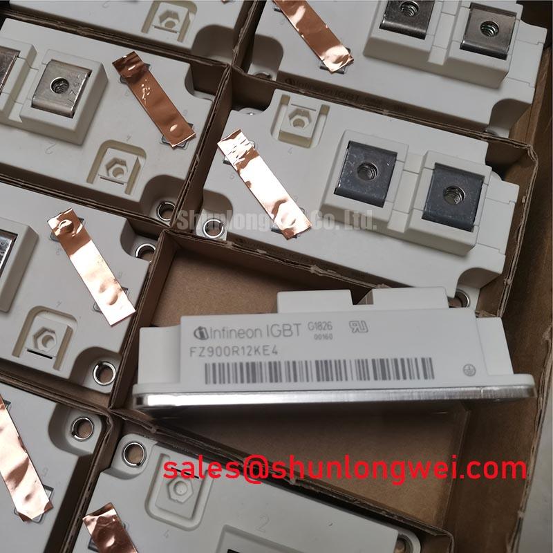
Infineon FZ900R12KE4 Single IGBT Module | 1200V 900A IHM-B
High-Current Switching with Advanced Trench/Fieldstop IGBT4 Technology
The Infineon FZ900R12KE4 represents a sophisticated engineering solution for high-power industrial conversion systems. This Single IGBT module leverages the 4th generation Trench/Fieldstop architecture, delivering a refined balance between low conduction losses and high switching ruggedness. Designed to operate at a nominal collector current of 900A under a 1200V blocking voltage, it is a primary building block for engineers managing megawatt-range power requirements.
- Core Specifications: 1200V | 900A | VCE(sat) 1.75V (typical)
- Key Advantages: Extended operating temperature up to 150°C for increased power density and optimized thermal management.
Engineers often ask, “How can I maintain system reliability while increasing current density in restricted cabinet spaces?” The FZ900R12KE4 answers this through its compact IHM-B package, which provides high power density without sacrificing the insulation integrity required for industrial environments.
Download Official FZ900R12KE4 Datasheet (PDF)

Technical Analysis: Thermal Robustness and Switching Efficiency
The FZ900R12KE4 is engineered with a focus on thermomechanical reliability. By integrating the Emitter Controlled 4 diode, the module achieves soft recovery characteristics, which significantly reduces electromagnetic interference (EMI) and voltage overshoots during high-speed switching. This is critical when designing intelligent IGBT drivers that must accurately monitor system health in real-time.
A central technical highlight is the module’s thermal resistance from junction to case ($R_{thJC}$). You can think of thermal resistance like the width of a highway exit ramp; a lower value (wider ramp) allows heat “traffic” to flow out of the semiconductor die more efficiently, preventing internal “bottlenecks” that lead to catastrophic failure. With a typical $R_{thJC}$ of 23.5 K/kW for the IGBT section, the FZ900R12KE4 ensures that peak losses are dissipated rapidly through the isolated baseplate.
Furthermore, the 10 µs short-circuit withstand time ($t_{psc}$) at 150°C provides a necessary safety window for protection circuits to intervene. This level of ruggedness is essential for high-power applications where load transients are frequent. The module’s ability to sustain high current pulses up to 1800A ($I_{CRM}$) allows for significant headroom during startup or heavy load steps, ensuring long-term IGBT reliability even under cyclic stress.


Optimized Application Scenarios
The FZ900R12KE4 is specifically characterized for environments demanding high current handling and extreme durability. Its technical profile makes it an ideal fit for the following sectors:
- Wind Turbines: The module’s high power cycling capability supports the variable load demands of renewable energy generation.
- Uninterruptible Power Supplies (UPS): Efficient switching reduces energy loss in large-scale data center protection systems.
- Solar Inverters: High current density allows for the design of more compact central inverters.
- Industrial Drives: Excellent ruggedness against short-circuits ensures longevity in motor control applications.
Best Match Conclusion: The FZ900R12KE4 is the optimal selection for megawatt-scale converters requiring the high current density and thermal stability of the IHM-B footprint.
Key Specifications and Ratings
| Parameter | Symbol | Value |
|---|---|---|
| Absolute Maximum Ratings ($T_vj = 25^circ C$) | ||
| Collector-Emitter Voltage | $V_{CES}$ | 1200 V |
| Continuous DC Collector Current | $I_{C,nom}$ | 900 A |
| Repetitive Peak Collector Current | $I_{CRM}$ | 1800 A |
| Electrical Characteristics (Typical) | ||
| Collector-Emitter Saturation Voltage | $V_{CE(sat)}$ | 1.75 V ($T_{vj}=125^circ C$) |
| Gate Threshold Voltage | $V_{GE(th)}$ | 5.1 V to 6.4 V |
| Thermal Characteristics | ||
| IGBT Thermal Resistance (per die) | $R_{thJC}$ | 23.5 K/kW |
| Operating Junction Temperature | $T_{vj,op}$ | -40 to 150 °C |
Engineer FAQ
Q1: What are the specific mounting requirements for the FZ900R12KE4 to ensure proper thermal contact?
A: According to the datasheet, the mounting torque for module-to-heatsink fixing should be between 3.00 Nm and 6.00 Nm (M6). Achieving uniform pressure is vital for minimizing thermal contact resistance. For more on this, refer to our guide on mastering thermal design.
Q2: Can the FZ900R12KE4 be paralleled for higher current requirements?
A: Yes, the Trenchstop IGBT4 technology features a positive temperature coefficient for $V_{CE(sat)}$, which naturally promotes current sharing between paralleled modules. However, symmetrical DC-link layout and balanced gate-drive impedance are required. See our insights on high-power IGBT paralleling for detailed layout strategies.
Q3: What is the isolation voltage rating for this module?
A: The FZ900R12KE4 features an isolation test voltage ($V_{ISOL}$) of 2.5 kV RMS at 50 Hz for 1 minute, ensuring robust electrical separation between the power terminals and the baseplate.
The Infineon FZ900R12KE4 provides engineers with a high-performance, thermally robust platform for heavy-duty power conversion. By combining 1200V Trenchstop technology with the standardized IHM-B package, it facilitates the development of efficient, durable systems for the most demanding industrial energy and traction applications.