“`json [ { “@context”: “https://schema.org”, “@type”: “Product”, “name”: “Toshiba MG100Q2YS42 IGBT Module”, “description”: “The Toshiba MG100Q2YS42 is a robust 1200V, 100A N-channel IGBT module in a half-bridge configuration, designed for high-power industrial systems. It integrates a complete half-bridge circuit into a single, isolated package, providing a durable solution for motor control, VFDs, and other high-power switching applications where efficiency and reliability are primary objectives.”, “mpn”: “MG100Q2YS42”, “model”: “MG100Q2YS42”, “brand”: { “@type”: “Brand”, “name”: “Toshiba” }, “category”: “Electronic Components > Power Semiconductors > IGBT Modules”, “image”: [ “https://www.slw-ele.com/wp-content/uploads/2023/05/IMG_0109.jpg”, “https://www.slw-ele.com/wp-content/uploads/2023/05/IMG_0110.jpg”, “https://www.slw-ele.com/wp-content/uploads/2023/05/IMG_0108.jpg” ], “subjectOf”: { “@type”: “WebPage”, “name”: “Official Datasheet (PDF) for Toshiba MG100Q2YS42”, “url”: “https://www.alldatasheet.com/datasheet-pdf/pdf/58797/TOSHIBA/MG100Q2YS42.html” }, “application”: [ “AC Motor Controls”, “Variable Frequency Drives (VFDs)”, “Welding Power Supplies”, “Uninterruptible Power Supplies (UPS)”, “Industrial Power Conversion Systems” ], “additionalProperty”: [ { “@type”: “PropertyValue”, “propertyID”: “VCES”, “name”: “Collector-Emitter Voltage”, “value”: “1200”, “unitCode”: “VLT”, “unitText”: “V” }, { “@type”: “PropertyValue”, “propertyID”: “IC”, “name”: “Collector Current (DC)”, “value”: “100”, “unitCode”: “AMP”, “unitText”: “A” }, { “@type”: “PropertyValue”, “propertyID”: “VCE(sat)”, “name”: “Collector-Emitter Saturation Voltage (Max)”, “value”: “3.6”, “unitCode”: “VLT”, “unitText”: “V”, “description”: “Measured at IC=100A, VGE=15V” }, { “@type”: “PropertyValue”, “propertyID”: “VGES”, “name”: “Gate-Emitter Voltage”, “value”: “±20”, “unitCode”: “VLT”, “unitText”: “V” }, { “@type”: “PropertyValue”, “propertyID”: “PC”, “name”: “Collector Power Dissipation”, “value”: “690”, “unitCode”: “WTT”, “unitText”: “W” }, { “@type”: “PropertyValue”, “propertyID”: “Tj”, “name”: “Operating Junction Temperature”, “minValue”: -40, “maxValue”: 150, “unitCode”: “CEL”, “unitText”: “°C” }, { “@type”: “PropertyValue”, “propertyID”: “Rth(j-c)”, “name”: “Thermal Resistance (Junction to Case, IGBT)”, “value”: “0.18”, “unitText”: “°C/W” }, { “@type”: “PropertyValue”, “propertyID”: “tf”, “name”: “Fall Time (Typical)”, “value”: “0.30”, “unitText”: “µs” }, { “@type”: “PropertyValue”, “propertyID”: “trr”, “name”: “Diode Reverse Recovery Time (Typical)”, “value”: “0.15”, “unitText”: “µs” }, { “@type”: “PropertyValue”, “name”: “Internal Configuration”, “value”: “Half-Bridge (2-in-1)” } ] }, { “@context”: “https://schema.org”, “@type”: “FAQPage”, “mainEntity”: [ { “@type”: “Question”, “name”: “What is the internal configuration of the MG100Q2YS42?”, “acceptedAnswer”: { “@type”: “Answer”, “text”: “The module contains two N-channel IGBTs connected in a half-bridge (or 2-in-1) configuration. Each IGBT is paired with an anti-parallel free-wheeling diode. The electrodes are electrically isolated from the mounting baseplate.” } }, { “@type”: “Question”, “name”: “How should I calculate the heatsink requirement for this IGBT module?”, “acceptedAnswer”: { “@type”: “Answer”, “text”: “To determine the required heatsink, you must first calculate the total power dissipation from both conduction and switching losses. Then, use the module’s thermal resistance from junction to case (Rth(j-c) = 0.18°C/W for the IGBT) along with the thermal resistance of your thermal interface material (TIM). The total thermal resistance from junction to ambient must be low enough to keep the junction temperature (Tj) below its maximum rating of 150°C under worst-case operating conditions.” } }, { “@type”: “Question”, “name”: “What are the key considerations for the gate drive circuit for the MG100Q2YS42?”, “acceptedAnswer”: { “@type”: “Answer”, “text”: “A gate driver capable of supplying a +15V turn-on voltage and a 0V to -15V turn-off voltage is recommended. Using a negative gate voltage for turn-off provides improved noise immunity against parasitic turn-on. The gate drive circuit layout should be designed to minimize loop inductance to prevent voltage ringing and ensure clean, reliable switching transitions.” } }, { “@type”: “Question”, “name”: “Is the MG100Q2YS42 module suitable for high-frequency (> 50 kHz) applications?”, “acceptedAnswer”: { “@type”: “Answer”, “text”: “While the MG100Q2YS42 has respectable switching speeds, its characteristics are optimized for low-to-moderate frequency applications, such as motor drives, which typically operate up to 20 kHz. For significantly higher frequencies (above 50 kHz), using an IGBT with lower switching losses (Eon/Eoff) would be more appropriate to effectively manage thermal dissipation.” } } ] } ] “`
Toshiba MG100Q2YS42 IGBT Module | 1200V 100A
Balanced Performance for High-Power Industrial Systems
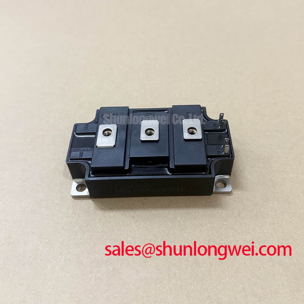
The Toshiba MG100Q2YS42 is a robust N-channel IGBT module that delivers a well-balanced combination of high voltage and current handling for industrial power conversion systems. This module integrates a complete half-bridge circuit into a single, isolated package, providing a durable solution for motor control and high-power switching. Its proven design offers a reliable foundation for systems where efficiency and dependable operation are primary objectives.
- Core Specifications: 1200V | 100A | VCE(sat) 3.6V (max)
- Key Advantages: Facilitates effective thermal management through low thermal resistance and offers balanced switching characteristics for moderate-frequency designs.
- Application Focus: The robust Safe Operating Area (SOA) makes it a strong candidate for controlling inductive loads in variable frequency drives (VFDs).
Download Official Datasheet (PDF)


Technical Analysis for System Integration
The engineering value of the MG100Q2YS42 is centered on its balanced electrical and thermal characteristics. The collector-emitter saturation voltage (VCE(sat)) is specified at a maximum of 3.6V at the nominal 100A collector current. This parameter is a primary determinant of conduction losses; a controlled VCE(sat) ensures that heat generation during the on-state is managed, contributing to overall system efficiency. This balance is critical in applications like high-frequency inverters where both conduction and switching losses impact performance.
Efficient heat extraction is fundamental to the reliability of any power module. The MG100Q2YS42 specifies a thermal resistance from junction to case (Rth(j-c)) of 0.18 °C/W for the IGBT portion. This value can be thought of like the width of a pipe for heat; a lower number signifies a wider pipe, allowing heat to flow more easily from the active semiconductor to the heatsink. This efficient thermal path is critical for maintaining the junction temperature within its specified maximum of 150°C, a key factor explored in IGBT thermal design guides.
The module’s switching characteristics are tailored for robust, moderate-frequency operation. With a typical fall time (tf) of 0.30 µs and a reverse recovery time (trr) of 0.15 µs for the integrated free-wheeling diode (FWD), the MG100Q2YS42 minimizes the time spent in the high-dissipation linear region during turn-off transitions. This controlled switching speed helps to limit losses without generating excessive EMI, a frequent challenge in power electronics that often requires careful gate resistor selection.
Optimized Application Scenarios
The specifications of the MG100Q2YS42 make it a suitable component for several high-power industrial applications:
- AC Motor Controls: Its 1200V collector-emitter voltage provides a sufficient safety margin to handle the voltage overshoots generated by inductive motor loads.
- Variable Frequency Drives (VFDs): The combination of a 100A current rating and efficient thermal dissipation allows for precise and reliable motor speed control under heavy loads.
- Welding Power Supplies: The module’s robust construction can withstand the high-current, pulsed-load conditions characteristic of inverter-based welding equipment.
- Uninterruptible Power Supplies (UPS): The dependable switching performance and current handling ensure stable power conversion, a critical requirement for UPS systems.
This module is best matched for systems requiring a proven, high-voltage IGBT with balanced performance for moderate switching frequencies and high-reliability industrial environments.
Key Specifications of the MG100Q2YS42
| Absolute Maximum Ratings (Tc = 25°C) | |
|---|---|
| Collector-Emitter Voltage (VCES) | 1200 V |
| Gate-Emitter Voltage (VGES) | ±20 V |
| Collector Current (DC) (IC) | 100 A |
| Collector Power Dissipation (PC) | 690 W |
| Operating Junction Temperature (Tj) | -40 to +150 °C |
| Electrical Characteristics (Tj = 25°C unless otherwise noted) | |
| Collector-Emitter Saturation Voltage (VCE(sat)) @ IC=100A, VGE=15V | 3.0 V (Typ), 3.6 V (Max) |
| Gate-Emitter Cut-off Voltage (VGE(off)) | 3.0 to 6.5 V |
| Diode Forward Voltage (VF) @ IE=100A | 2.0 V (Typ), 2.5 V (Max) |
| Input Capacitance (Cies) | 10000 pF (Typ) |
Engineer’s FAQ
What is the internal configuration of the MG100Q2YS42?
The module contains two N-channel IGBTs connected in a half-bridge (or 2-in-1) configuration. Each IGBT is paired with an anti-parallel free-wheeling diode. The electrodes are electrically isolated from the mounting baseplate.
How should I calculate the heatsink requirement for this IGBT module?
To determine the required heatsink, you must first calculate the total power dissipation (conduction and switching losses). Then, use the specified thermal resistance from junction to case (Rth(j-c) = 0.18°C/W for the IGBT) and the thermal resistance of your thermal interface material (TIM). The total thermal resistance (Junction-to-Ambient) must be low enough to keep the junction temperature (Tj) below 150°C under worst-case operating conditions.
What are the key considerations for the gate drive circuit?
A gate driver capable of supplying a +15V turn-on voltage and a 0V to -15V turn-off voltage is recommended. A negative gate voltage provides improved noise immunity against parasitic turn-on. The gate drive circuit layout should minimize loop inductance to prevent voltage ringing and ensure clean switching transitions.
Is this module suitable for high-frequency ( > 50 kHz) applications?
While the MG100Q2YS42 has respectable switching speeds, its characteristics are optimized for low-to-moderate frequency applications such as motor drives (typically up to 20 kHz). For significantly higher frequencies, IGBTs with lower switching losses (Eon/Eoff) might be more appropriate to manage thermal dissipation.
Enabling Robust Power System Design
The Toshiba MG100Q2YS42 provides a technically sound and reliable component for industrial power electronics. Its integration of two IGBTs and diodes into an isolated module simplifies mechanical assembly and thermal design. By offering a balanced set of voltage, current, and switching parameters, this module allows engineers to develop efficient and durable power conversion systems for demanding industrial environments.