Toshiba MG150Q2YS51 IGBT Module: A Technical Review for Industrial Applications
Toshiba MG150Q2YS51 IGBT Module | 1200V 150A
Introduction and Core Highlights
The Toshiba MG150Q2YS51 is a robust N-Channel Insulated Gate Bipolar Transistor (IGBT) module delivering a balanced performance profile for high-power industrial applications. It integrates two IGBTs in a half-bridge configuration, providing a foundational building block for inverter and motor control systems. Its primary value lies in its combination of high voltage and current ratings, ensuring reliable power handling in demanding electrical environments. Understanding its thermal characteristics is key to maximizing system longevity.
- Core Specifications: 1200V | 150A | VCE(sat) 3.0V (max)
- Key Advantages: High breakdown voltage for system safety, substantial current capacity for medium-power motors.
- Primary Function: Serves as a high-power electronic switch in three-phase inverters and converters.
Download Official Datasheet (PDF)
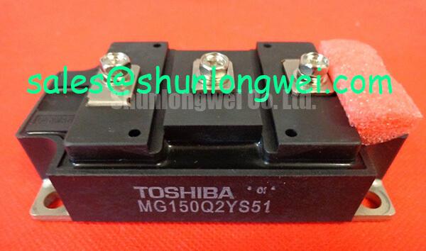
Technical Analysis of the MG150Q2YS51
The engineering value of the MG150Q2YS51 is defined by its core electrical and thermal parameters. A collector-emitter voltage (V_CES) of 1200V provides a significant safety margin for systems operating on 400V or 480V AC lines. This high breakdown voltage is crucial for withstanding voltage spikes that commonly occur in inductive motor loads, directly contributing to system robustness and preventing catastrophic failure. Combined with a continuous collector current (I_C) rating of 150A, this module is well-equipped to manage the power requirements of medium-sized industrial machinery.
A critical parameter for thermal design is the collector-emitter saturation voltage, or V_CE(sat), specified at a maximum of 3.0V at 150A. This value represents the voltage drop across the IGBT when it is fully turned on. You can think of V_CE(sat) as the friction inside a pipe; a lower value means less resistance and therefore less energy lost as heat. This 3.0V figure is the basis for calculating conduction losses, which is essential for selecting an adequate heatsink. Efficient thermal management is fundamental to achieving long operational life.
The module’s switching characteristics, with turn-on and fall times specified around 1.0 µs, define its operational sweet spot. These speeds are well-suited for applications with switching frequencies in the low-to-mid kilohertz range, typical for Variable Frequency Drives (VFDs) and industrial inverters. While not designed for ultra-high-frequency applications, this deliberate design choice offers a good balance between switching losses and conduction losses, optimizing overall system efficiency for its target applications.
Optimized Application Scenarios
The specifications of the MG150Q2YS51 make it a strong candidate for several high-power industrial applications:
- AC Motor Drives: Its 1200V/150A rating is ideal for controlling three-phase induction motors, providing the necessary power and voltage headroom for precise speed and torque control.
- Uninterruptible Power Supplies (UPS): The module’s capacity to handle high currents makes it suitable for the inverter stage of a UPS, ensuring a stable and reliable power backup.
- Welding Power Supplies: The device can reliably manage the high-current pulses required in various welding processes, supported by its robust thermal design.
- General-Purpose Power Converters: Its versatile and balanced performance allows for integration into a wide range of DC-AC or DC-DC power conversion systems.
This module is best matched for systems requiring robust, reliable power switching at frequencies below 20 kHz under demanding industrial conditions.
Key Specification Parameters
| Absolute Maximum Ratings (Ta = 25°C) | |
|---|---|
| Collector-Emitter Voltage (V_CES) | 1200 V |
| Gate-Emitter Voltage (V_GES) | ±20 V |
| Collector Current (DC) (I_C) | 150 A |
| Collector Power Dissipation (P_C) | 830 W |
| Operating Junction Temperature (T_j) | 150 °C |
| Electrical Characteristics (Ta = 25°C) | |
| Collector-Emitter Saturation Voltage (V_CE(sat)) | 3.0 V (Max) @ IC = 150A |
| Gate-Emitter Leakage Current (I_GES) | ±500 nA (Max) @ VGE = ±20V |
| Turn-On Time (t_on) | 1.0 µs (Max) |
| Fall Time (t_f) | 1.0 µs (Max) |
| Diode Forward Voltage (V_ECF) | 2.5 V (Max) @ IEC = 150A |
| Thermal Characteristics | |
| Thermal Resistance (Junction to Case) (R_th(j-c)) – IGBT | 0.15 °C/W (Max) |
| Thermal Resistance (Junction to Case) (R_th(j-c)) – Diode | 0.30 °C/W (Max) |
Engineer’s FAQ
1. What is the practical maximum switching frequency for the MG150Q2YS51?
Based on the datasheet’s switching times (t_on, t_off, t_fall), this module is optimized for lower frequency applications. While a theoretical maximum can be high, for practical industrial designs aiming for good efficiency and thermal stability, operating frequencies are typically kept below 20 kHz. Exceeding this range significantly increases switching losses, leading to excessive heat generation.
2. How do I perform a basic thermal calculation for this IGBT module?
To select a proper heatsink, you must calculate the total power dissipation. First, calculate conduction losses: P_cond = V_CE(sat) * I_C * Duty Cycle. Second, estimate switching losses, which depend heavily on frequency and test conditions (E_on + E_off) * f_sw. The total power loss is P_total = P_cond + P_sw. Then, use the thermal resistance R_th(j-c) of 0.15 °C/W to determine the case temperature and select a heatsink that keeps the junction temperature (Tj) well below the 150°C maximum rating.
3. Can the MG150Q2YS51 be connected in parallel to achieve higher current?
Yes, paralleling is feasible. The datasheet’s output characteristics show that at high currents (above ~50A), V_CE(sat) has a positive temperature coefficient. This means as a device heats up, its on-state resistance increases slightly, which naturally helps balance current sharing between parallel modules. However, for successful IGBT paralleling, a symmetrical PCB layout and careful gate drive design are essential to minimize mismatched switching behavior.
4. What is the purpose of the integrated free-wheeling diode (FWD)?
The FWD is critical in inverter circuits that drive inductive loads like motors. When the IGBT turns off, the energy stored in the motor’s inductance creates a current that needs a path to flow. The FWD provides this path, preventing a large voltage spike across the IGBT that could otherwise destroy it. The performance of this diode, particularly its recovery time (t_rr), is important for system efficiency.
System Design Enablement
The Toshiba MG150Q2YS51 offers a proven and effective solution for power electronics engineers tasked with developing medium-power industrial systems. Its straightforward integration, combined with a solid foundation of high voltage and current ratings, enables the design of reliable and efficient motor drives and power inverters without the complexity of the very latest, high-frequency-optimized technologies. This focus on balanced, core performance makes it a dependable workhorse component.