MBR60045CT: A High-Current, Low-Loss Rectifier for Efficient Power Conversion
“`html
MBR60045CT 45V 600A Schottky Barrier Rectifier Module
Introduction and Core Highlights
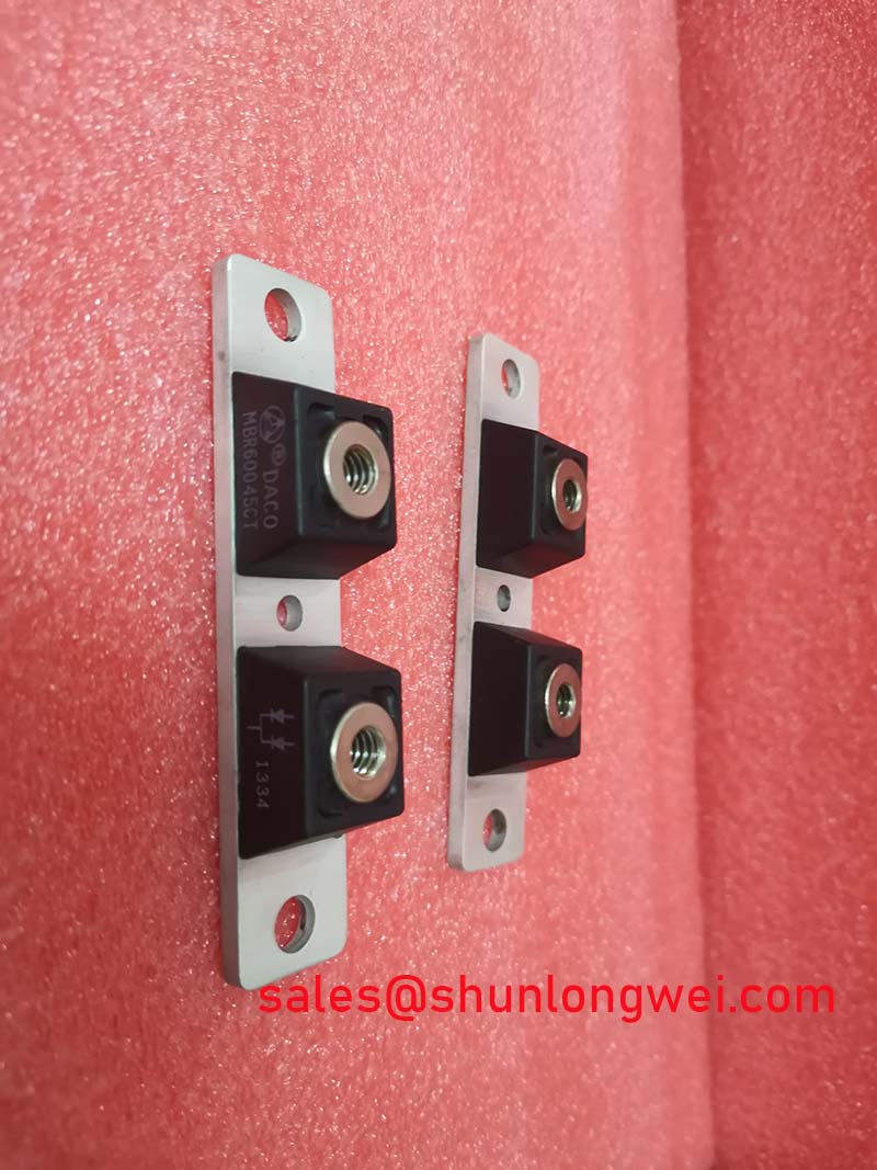
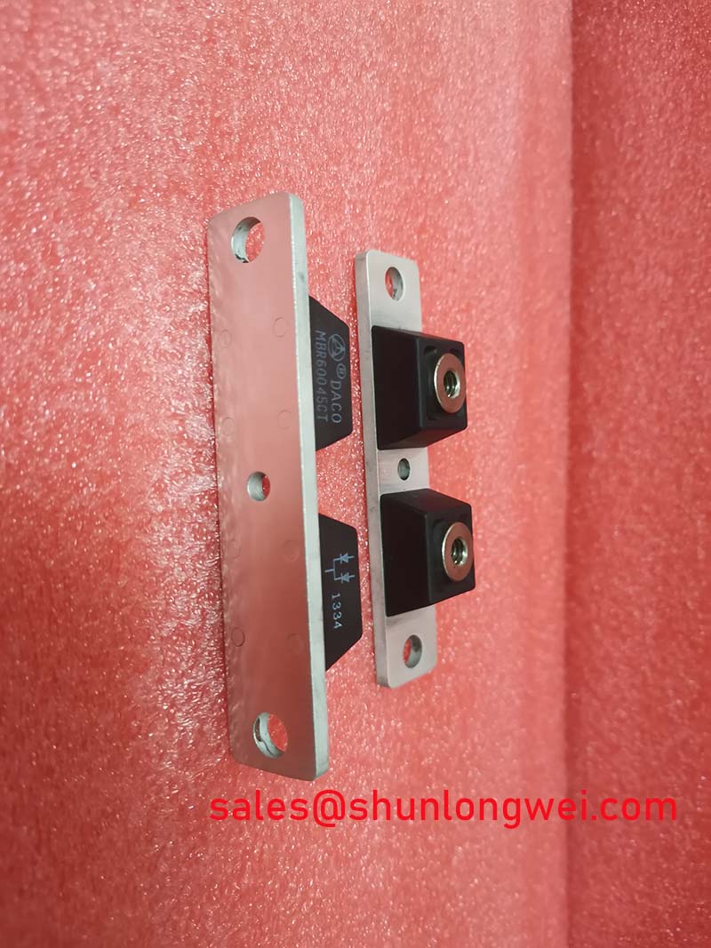
The Americasemi MBR60045CT is a dual common cathode Schottky barrier rectifier module engineered for exceptional efficiency in high-current power systems. Its primary value proposition is the extremely low forward voltage drop, which significantly reduces conduction losses and thermal management requirements. This device provides a robust solution for engineers seeking to enhance power density and system reliability in demanding applications.
- Core Specifications: 45V | 600A (300A per Diode) | VF (max) @ 300A: 0.65V
- Key Engineering Advantages: Minimizes conduction power loss and heat generation, and the high surge capability enhances system survivability during transient events.
For engineers evaluating components for high-current output stages, the low VF directly contributes to higher efficiency, as less power is dissipated as heat. For detailed electrical and thermal performance curves, download the official datasheet (PDF).


Technical Analysis: Efficiency and Robustness
The defining characteristic of the MBR60045CT is its exceptionally low forward voltage drop (VF), specified at a maximum of 0.65V at a high forward current of 300A and a junction temperature of 125°C. This parameter is critical for efficiency. Think of forward voltage as electrical friction; a lower value means less energy is converted into waste heat as current passes through the device. This directly reduces power dissipation (PD = VF × IF), allowing for smaller heatsinks, higher power density, and lower operating temperatures, which is fundamental to long-term component reliability.
Beyond efficiency, the device is built for resilience in electrically demanding environments. It features a non-repetitive peak surge current (IFSM) rating of 3500A. This high surge immunity ensures the rectifier can withstand large, brief inrush currents that are common during the startup of capacitive loads or in short-circuit conditions. This robustness is essential for applications like switched-mode power supplies. The module is housed in an industry-standard SOT-227 (PRM5) package with an isolated baseplate providing 2500V RMS isolation, simplifying assembly and thermal management by allowing direct mounting to a common chassis or heatsink.
Optimized Application Scenarios
- Switched-Mode Power Supplies (SMPS): As an output rectifier, its low VF dramatically improves the efficiency of the DC output stage, a critical factor in high-power SMPS design.
- High-Current DC-DC Converters: The 600A total current handling capability makes it an excellent choice for the output stages of high-current buck or boost converters.
- Freewheeling and Polarity Protection Diodes: The high surge rating (IFSM) allows it to safely clamp voltage spikes from inductive loads in motor drives or serve as a robust reverse polarity protection diode in battery systems.
- Welding and Plating Power Systems: Capable of handling the high continuous and pulsed currents required in welding inverters and electroplating rectifiers while maintaining high efficiency.
This rectifier is best matched for high-current power systems where minimizing conduction losses and ensuring thermal stability are primary design objectives.
Key Specifications of the MBR60045CT
| Absolute Maximum Ratings | |
|---|---|
| Repetitive Peak Reverse Voltage (VRRM) | 45 V |
| Average Forward Current (IF(AV)) per diode @ TC=120°C | 300 A |
| Total Average Forward Current (IF(AV)) @ TC=120°C | 600 A |
| Peak Surge Forward Current (IFSM), 8.3ms sine | 3500 A |
| Operating Junction Temperature (TJ) | -55 to +150 °C |
| Electrical & Thermal Characteristics (Per Diode) | |
| Max Forward Voltage (VF) @ 300A, TJ=25°C | 0.75 V |
| Max Forward Voltage (VF) @ 300A, TJ=125°C | 0.65 V |
| Max Reverse Current (IR) @ 45V, TJ=125°C | 100 mA |
| Thermal Resistance, Junction to Case (Rth(j-c)) | 0.12 °C/W |
| Isolation Voltage (VISOL) | 2500 V (RMS) |
Engineer’s FAQ
1. How does the low forward voltage of the MBR60045CT impact heatsink selection?
The low VF (0.65V at 300A, 125°C) directly reduces conduction power loss (PD = VF × IF). For example, at 300A, the dissipation per diode is approximately 195W. A higher VF device would generate significantly more heat under the same conditions, necessitating a larger, more expensive heatsink or more complex cooling solutions to maintain the same junction temperature. The MBR60045CT’s efficiency allows for a more compact and cost-effective thermal design.
2. What are the mounting torque recommendations for the SOT-227 package?
According to the datasheet, the recommended mounting torque for the M3 screw is between 1.5 and 1.7 Newton-meters (Nm), or 13 to 15 inch-pounds (lbf-in). Applying the correct torque is critical to ensure optimal thermal contact between the module’s baseplate and the heatsink without causing mechanical stress to the package.
3. Can the two internal diodes be connected in parallel?
The datasheet does not explicitly state that the internal diodes are tested or matched for paralleling. While the common cathode configuration is convenient, paralleling the two diodes to achieve a single 600A device is generally not recommended without careful consideration of current sharing. Even small mismatches in VF can lead to one diode carrying more current, potentially causing thermal runaway. If paralleling is necessary, it requires careful thermal and electrical layout to balance the load.
4. Is the MBR60045CT suitable for high-frequency applications?
Yes, as a Schottky rectifier, it has negligible reverse recovery time, which is a significant advantage over standard silicon diodes in high-frequency circuits. The absence of reverse recovery charge (Qrr) eliminates associated switching losses and EMI, making it well-suited for high-frequency SMPS and DC-DC converters where fast switching is essential for efficiency and compact magnetics.
Concluding Statement
For engineers developing high-current power conversion systems, the MBR60045CT provides a clear path to achieving superior efficiency and thermal performance. The device’s low conduction losses and robust electrical characteristics, contained within a standard isolated package, enable the design of more compact, reliable, and energy-efficient power electronics.
“`