MG150Q2YS40 IGBT Module: Technical Analysis for High-Power Applications
## MG150Q2YS40 1200V 150A Dual IGBT Module by Toshiba
An Engineered Solution for Robust High-Power Switching
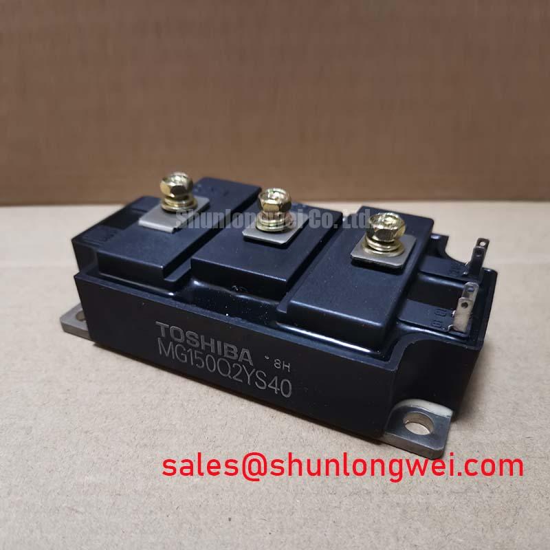
The Toshiba MG150Q2YS40 is a Silicon N Channel IGBT module designed for durability in demanding industrial applications. It integrates two IGBTs into a half-bridge configuration, providing a robust building block for high-power inverters and motor controllers. With its high voltage and current ratings, this module is engineered to deliver reliable performance where operational stability is a primary design criterion.
- Core Specifications: 1200V | 150A | 4.0V Max VCE(sat)
- Key Advantages: Isolated base for simplified thermal mounting, integrated half-bridge circuit reduces external component count.
This module’s electrical and thermal characteristics are well-suited for engineers developing or maintaining systems like Variable Frequency Drives (VFDs), where predictable performance under heavy loads is essential.
Download the official MG150Q2YS40 Datasheet (PDF)



Technical Analysis for System Integration
The MG150Q2YS40 is defined by its substantial power handling capability. The collector-emitter voltage (V_CES) rating of 1200V provides a significant safety margin for systems operating on 400V or 480V AC lines, protecting against transient voltage spikes. The 150A continuous collector current rating enables the control of high-power industrial motors and other demanding loads. These ratings establish the module as a foundational component for robust power conversion.
A critical parameter for thermal design is the junction-to-case thermal resistance (Rth(j-c)). For the IGBT in this module, the Rth(j-c) is specified at 0.11 °C/W. Think of thermal resistance as the narrowness of a pipe; a lower value signifies a wider pipe, allowing heat to escape more easily. This specified value is essential for engineers to accurately calculate heatsink requirements, ensuring the junction temperature remains within the safe operating area and preventing thermal wear-out over the long term. The module’s isolated base further simplifies this process by providing 2500V (AC, 1 minute) of isolation between the terminals and the mounting plate.
Optimized Application Scenarios
The specifications of the MG150Q2YS40 make it a suitable choice for a range of industrial power systems:
- Industrial Motor Controls: Its 1200V/150A capability and integrated half-bridge are ideal for building the inverter stage of VFDs that control large AC induction motors.
- High-Power Switching Supplies: The module can function as the primary switching element in uninterruptible power supplies (UPS) and industrial welding equipment.
- Servo Amplifiers: The robust construction handles the dynamic and often heavy loads characteristic of industrial servo systems.
This module is best matched for applications where durability and straightforward thermal management are prioritized over cutting-edge switching efficiency.
Key Specifications of the MG150Q2YS40
| Absolute Maximum Ratings (Ta = 25°C) | ||
|---|---|---|
| Collector-Emitter Voltage | V_CES | 1200 V |
| Gate-Emitter Voltage | V_GES | ±20 V |
| Collector Current (DC) | I_C | 150 A |
| Collector Power Dissipation (Tc=25°C) | P_C | 1130 W |
| Electrical & Thermal Characteristics (Tj = 25°C unless otherwise specified) | ||
| Collector-Emitter Saturation Voltage (Max) | V_CE(sat) | 4.0 V (at I_C = 150A) |
| Gate-Emitter Cut-off Voltage | V_GE(off) | 3.0 V to 6.0 V |
| Diode Forward Voltage (Max) | V_F | 3.0 V (at I_F = 150A) |
| Thermal Resistance (Junction to Case, IGBT) | Rth(j-c) | 0.11 °C/W |
| Short Circuit Withstand Time | t_sc | 10 µs (at Vcc=600V, Vge=15V) |
Engineer’s FAQ
Q: How do I perform a basic thermal calculation for the MG150Q2YS40?
A: To estimate heatsink requirements, first calculate the power dissipation (P_diss), which is primarily conduction loss (V_CE(sat) * I_C) plus switching losses. Then, use the formula: T_j = T_a + P_diss * (Rth(j-c) + Rth(c-s) + Rth(s-a)). T_j is the junction temperature (max 150°C), T_a is ambient temperature, Rth(j-c) is given as 0.11 °C/W, Rth(c-s) is for thermal grease, and Rth(s-a) is for the heatsink. You must solve for Rth(s-a) to select an appropriate heatsink. For detailed calculations, refer to the thermal characteristics curves in the official datasheet.
Q: What is the recommended mounting torque for this module?
A: According to the datasheet, the recommended torque for the mounting screws (M6) is 3.0 to 4.0 N·m. The terminal screws (M6) should be tightened to the same torque. Applying the correct torque is crucial for ensuring good thermal contact and preventing mechanical stress. Explore our guide on mastering IGBT thermal design for more context.
Q: Is this module suitable for high-frequency ( > 20 kHz) applications?
A: The MG150Q2YS40 is specified with typical turn-off times (t_off) of 0.8 µs. While suitable for motor control frequencies (typically a few kHz), its switching losses will increase significantly at higher frequencies. For applications above 20 kHz, a newer generation of IGBTs with lower VCE(sat) and faster switching speeds would likely provide better efficiency.
Q: What is the function of the integrated Free-Wheeling Diode (FWD)?
A: The FWD provides a path for the inductive current to flow when the IGBT is turned off in an inverter circuit. This is essential to prevent a massive voltage spike across the IGBT, which could otherwise destroy the device. The MG150Q2YS40 includes a co-packaged FWD matched to the IGBT’s performance.
Enabling Reliable Power Conversion
The MG150Q2YS40 provides a proven, durable solution for engineers tasked with designing high-power industrial systems. Its straightforward integration, defined thermal characteristics, and robust electrical ratings allow for the creation of power stages that prioritize long-term operational reliability.