MMG75S170B: A Technical Review of a Robust 1700V IGBT Module
MMG75S170B: 1700V 75A IGBT Module for High-Voltage Systems
Introduction and Core Highlights
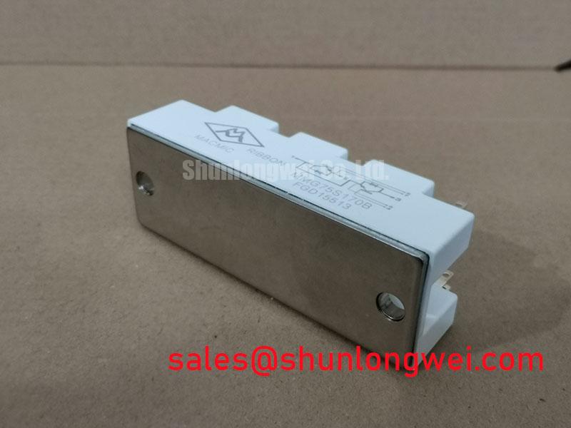
The MacMic MMG75S170B is a half-bridge IGBT module engineered for robust performance in high-voltage power conversion systems. Its primary value proposition lies in the use of highly rugged SPT+ (Soft Punch Through) chip technology, which provides a high short-circuit capability and a VCE(sat) with a positive temperature coefficient, ensuring stability and durability in demanding industrial environments. This design facilitates reliable operation, particularly when paralleling devices for higher power outputs.
- Core Specifications: 1700V | 75A | VCE(sat) 2.4V (typ)
- Key Advantages: High short-circuit tolerance, stable current sharing in parallel operation.
This module provides the necessary voltage margin for systems operating on higher voltage buses, such as 690V AC mains. For detailed electrical and thermal characteristics, Download the Official Datasheet (PDF).


Technical Analysis for System Reliability
A critical feature of the MMG75S170B is its collector-emitter saturation voltage (VCE(sat)) having a positive temperature coefficient. This characteristic is fundamental for high-power applications where multiple IGBT modules are connected in parallel. As a module’s temperature increases, its on-state voltage drop also increases, naturally forcing current to share more evenly with cooler, parallel devices. This self-regulating behavior prevents thermal runaway in a single module, a common failure mode in designs that require IGBT paralleling for increased current capacity.
The module’s thermal resistance from junction to case (Rth(j-c)) for the IGBT is specified at 0.48 K/W. Think of thermal resistance as the width of a pipe for heat flow; a lower value signifies a wider pipe, allowing heat to escape the semiconductor junction more efficiently. This efficient heat transfer is crucial for maintaining the junction temperature below the maximum rating of 175°C, ensuring operational longevity. Effective thermal management is key to leveraging the full performance of this module.
Optimized Application Scenarios
The specifications of the MMG75S170B make it a strong candidate for several high-voltage industrial applications:
- AC Motor Drives: The 1700V rating provides a secure voltage margin for inverters driving 690V AC industrial motors, protecting against DC-bus voltage spikes.
- Uninterruptible Power Supplies (UPS): Its robust build and stable thermal characteristics ensure reliable operation in high-voltage UPS systems where uptime is critical.
- Renewable Energy Systems: Suitable for solar inverters and fuel cell converters connected to high DC voltage arrays, offering dependable power conversion.
- Motion/Servo Control: The fast and soft reverse recovery characteristics of the integrated freewheeling diodes reduce switching losses and EMI, beneficial for precision control systems.
This module is best matched for high-reliability power systems where a high blocking voltage and stable thermal performance are the primary design considerations.
Key Specification Parameters
| Absolute Maximum Ratings (Tc = 25°C) | |
|---|---|
| Collector-Emitter Voltage (VCES) | 1700 V |
| Continuous Collector Current (IC) @ Tc=100°C | 75 A |
| Gate-Emitter Voltage (VGES) | ±20 V |
| Power Dissipation per IGBT (Ptot) | 535 W |
| Electrical Characteristics (Tj = 25°C unless otherwise specified) | |
| Collector-Emitter Saturation Voltage (VCE(sat)) @ IC=75A, VGE=15V | 2.4 V (Typ.) / 2.75 V (Max.) |
| Gate-Emitter Threshold Voltage (VGE(th)) @ IC=3mA | 5.4 V (Typ.) |
| Collector Cut-off Current (ICES) @ VCE=1700V | 5.0 mA (Max.) |
| Turn-on Delay Time (td(on)) @ Inductive Load | 80 ns (Typ.) |
| Turn-off Delay Time (td(off)) @ Inductive Load | 420 ns (Typ.) |

Engineer’s FAQ
- How does the Rth(j-c) value influence heatsink selection?
- The thermal resistance junction-to-case (Rth(j-c)) of 0.48 K/W for the IGBT is a key input for thermal calculations. To select a heatsink, you must first calculate the total power loss (conduction and switching). This power loss, multiplied by the sum of Rth(j-c) and the thermal resistance of the heatsink, determines the junction temperature rise. A lower Rth(j-c) allows for a smaller, more cost-effective heatsink to maintain the junction temperature below its 175°C maximum.
- What are the recommended gate drive voltage levels?
- The datasheet specifies tests with a gate-emitter voltage (VGE) of ±15V. The gate-emitter threshold voltage (VGE(th)) has a typical value of 5.4V. A +15V turn-on voltage is standard for driving this module to achieve the rated VCE(sat). A negative turn-off voltage (e.g., -8V to -15V) is recommended to ensure fast turn-off and prevent parasitic turn-on, an issue that can be better understood through resources on negative gate voltage.
- Is this module suitable for high-frequency switching?
- The MMG75S170B is optimized for robustness and low conduction loss rather than very high-frequency operation. With a typical turn-off delay time of 420 ns, it is well-suited for applications with switching frequencies in the low to medium kHz range, typical of industrial motor drives and some renewable energy inverters. Designs requiring higher frequencies might need to evaluate the switching losses (Eon and Eoff) carefully.
System Design Enablement
The MMG75S170B IGBT module offers a solid foundation for power electronics engineers tasked with designing high-voltage, high-reliability systems. Its use of proven SPT+ technology provides a high safety margin against short-circuit events, while its positive VCE(sat) temperature coefficient simplifies the design of high-current systems requiring paralleled modules. This focus on durability and stable operation allows designers to build robust and long-lasting power conversion solutions.