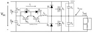

It does this by supplementing a conventional three-phase bridge, albeit silicon carbide bridge in this case, with three auxiliary resonant circuits, one per phase, that briefly divert current from the main bridge transistors just before they commutate.
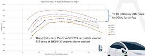

To explain the 18 mosfets: each mosfet in the three-phase bridge is actually a parallel triplet, and the six auxiliary silicon IGBTs are actually parallel pairs in the 200kW design, which was run at 100kW for the efficiency demo. The bridge mosfets only have to be sized for conduction losses, not switching losses, and the auxiliary silicon IGBTs are much smaller than the bridge switches as they only have to deal with their own switching losses plus brief full-current conduction. Diodes D1 and D2 in the top diagram have to be added for ARCP. They are silicon carbide, and small as they only have to conduct for 1μs per cycle. The company claims that a similar hard-switched inverter would need 36x 35mΩ die, and could only run at 10kHz – with 10kHz operation, compared with 100kHz, needing a 10x bigger dc link capacitor.

According to Pre-Switch, ARCP was invented in the 1980s by General Electric, but no reliable way could be found to pre-emptive time the auxiliary circuit accurately: “First, the system has limited access to parameters, in a noisy environment, and therefore must operate with degrees of uncertainty. Second, as reactive behaviour can never be ‘on time’, the system must pre-act – signals must launch without a well-defined stimulus to indicate when to act.”
What made control possible for Pre-Switch was a shift to artificial intelligence. “Making ZVS [zero-voltage switching] a reality requires a system that is statistical in adaptation and predictive in nature, an ideal application for AI”, according to the company.
“The Pre-Switch AI engine uses in-exact data read from a noisy environment, learn, story and plan for the next switching cycle of the transistor,” Pre-Switch CEO Bruce Renouard told Electronics Weekly. “There is a general deterministic output, but the AI has to send the gate drive signal prior to knowing, for sure, what is the precise timing needed for perfect soft-switching. All results are fed back into our algorithm to predict the next timing necessary given the changing inputs or output loads – this includes changes in temperature, device degradation, input voltage, PWM demands, output load and error conditions.”

The techniques are also applicable to power bridges made with traditional IGBTs.
“Pre-Switch eliminates 99% or 99.999% of SiC switching losses,” said Renouard. “The same technology with a different algorithm can eliminate 70-80% of IGBT switching losses. The reason IGBTs are are not 99% is because they have a long turn-off tail current which is today not able to be reduced by soft switching. Interestingly, we would prefer IGBT manufacturers to turn-on slowly and turn-off fast to help solve this problem.”
The algorithm also affects the auxiliary switches.
“The [auxiliary] IGBTs can be sized to accommodate most power ranges from 50kW to 400kW. We did a 500kW design that used two IGBTs in parallel for the resonant switches – four in total per phase – but we can also likely go back the two per phase with our newest AI,” he said.
Why not resonate the main bridge instead of adding an auxiliary circuit?
Today we are not aware of any soft-switching topology that can be used to build a DC to AC inverter. The market is all hard-switched for anything needing motor control. There are some markets, like solar inverter for industrial applications, that are using three-level converters to try to improve on the quality of the sine wave output. These multi-level inverters are very complex – they have 4-16x more switches and independent gate drivers, and are hard to control – but they do work. The Pre-Switch solution produces higher efficiency than a five-level inverter, and can be used for any application. By adding six IGBTs and associated diodes, Pre-Switch technology reduces the amount of total working switches by more than half, and allows the engineer to switch at 10x or more frequency.
Pre-Switch claims its topology provides a “lossless dV/dt filter” – what it that?
All electric motors have a specified maximum dV/dt that an inverter must say below to ensure that the insulation in the electric motor is not damaged. The spec is usually something like 5V/ns max. This is because high dV/dt and corresponding high di/dt are detrimental to motor reliability and are responsible for the top two reasons electric motors fail: High dV/dt causes motor insulation break down, and high di/dt causes bearing failures through electro-chemical etching.
To solve these problems, motor and inverter manufacturers have tried many different solutions. One is to use thicker insulation, but this adversely affects motor winding density which reduces motor efficiency and hurts power density. The other is to use ceramic bearings which costs money.
In industrial markets where the variable frequency drive is place at a distance from the electric motor, dV/dt becomes an even larger issue because the voltage can bounce back and amplify itself causing even more problems.
To solve this issue for industrial applications, companies offer an add-on dV/dt filter. These are costly at ~$1,600 – 2,000 for a 100kW-200kW electric motor, and usually cost another 1-2% efficiency across the full power range.
In the e-mobility space, the solution is to put the motor very close to the inverter and keep the dV/dt below the insulation threshold.
Pre-Switch has capacitors added across the working switches – something you would never do with a hard-switched inverter because inverter efficiency would plummet – which slow the rise of the voltage and current edges and can reduce or eliminate the transistor overshoot. This is a lossless process. In essence, we slow the edge speeds down but increase the transistor switching speeds and have virtually no switching losses. This is an artifact of pre-switching – other dc-dc and LLC soft-switching architecture do not solve the dV/dt or di/dt problems.
Pre-Switch CEO Bruce Renouard explains the additional power components required for ARCP, which the company sells as a hardware module dubbed RPG:
- Two IGBT switches and two SiC diodes per phase.
“These are low cost because they are pulse-rated, only operating for a maximum 1μs per switching cycle or less, and are at half the voltage of the main working fets,” said Renouard . - Resonant capacitors
“These are placed across the working fets and are varied by design goals to slow the di/dt and dV/dt. They are also used to hold the swing voltage across the working fets to zero volts each switching cycle during the 1μs swing period.” - The resonant Inductor (one per phase)
“These provide the load current and a little more current which is required to swing the voltage in the capacitors so that there is no voltage across the working fets. This is only operational for the 1μs or less.” - Gate drivers for both the IGBTs listed above and the drivers for the working FETs.