Personal and commercial transportation currently contributes to almost a third of greenhouse gas (GHG) emissions. Some obstacles to the wider adoption of electric vehicles (EVs) include the battery range, the charging time, and the charging infrastructure.
Standards for passenger electric vehicles (EVs) are now better defined, with the Charging Interface Initiative (CharIN) task force developing the Combined Charging System (CCS) specification, which allows for DC fast charging (DCFC) at power levels up to 350 kW at bus voltages of 800 V. These power levels adequate for most EV passenger cars with motors in the 100 kW range and battery capacities of 50 to 100 kWh.
Heavy-duty trucks for commercial transportation typically consume about 2 kWh/km and can have battery capacities of around 500 kWh. This leads to the requirement for MW charging levels. The Megawatt Charging System (MCS) is an evolving, high-power heavy-duty truck and bus EV charging standard created by CharIN. This article will highlight a presentation titled “MW-Chargers for heavy-duty EVs” delivered by Dr. Martin Schulz, Global Principal Application Engineer, Littelfuse at the PCIM Europe 2023 conference.
Charging Standards
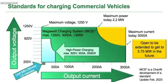
The MCS draft standards for power levels, connector styles, cooling requirements, etc. are still in flux, though initial guidelines list a maximum voltage of 1250 V and a current level of 3000 A (DC). Figure 1 shows the current CCS and MCS voltage and current levels for EV charging.

Traditional EV Chargers
Charging systems need galvanic isolation for safety and a traditional approach has taken the incoming power supply through a Power Factor Correction (PFC) rectification stage. This could be followed with an isolated DC-DC converter such as a dual active bridge or a LLC stage, as shown in Figure 2.


Silicon carbide (SiC) offers many advantages over traditional silicon-based IGBTs in the power conversion stages, such as much lower losses at a given power rating, the ability to switch faster and hence reduce the size of the magnetics, and improved high-temperature operation. Each charger unit shown in Figure 2 can typically provide 60 to 100 kW and would need to be stacked to achieve the net power requirement and system redundancy. Efficiencies are reported in the 97-98% range. While these SiC chargers enable compact, high power densities for passenger EV DCFC, the question is whether they would also suit the higher powers required for MCS.
Thyristors
Thyristors are four-layer, three-terminal, bipolar, current-controlled devices first commercialized in 1958. Excellent bipolar current conduction has allowed current and voltage ratings as high as 6000 A and 12000 V to be achieved in Si thyristors1. Rectifiers based on thyristors are key components in applications such as electrolysis. Medium voltage drives use load-commutating thyristor-based inverters in applications such as compressors and marine drives with powers ranging up to 100 MW. Very high-power thyristor-based converters are used in High Voltage Direct Current (HVDC) and Flexible AC Transmission Systems (FACTS), where they switch at the line frequency of 50-60 Hz. Their bi-directional voltage-blocking capability allows for line commutation. High reliability, efficiency, overload, and surge current capability give them unparalleled advantages in such applications.
MW-Chargers for Heavy-Duty EVs using Thyristors
Littelfuse has proposed an MW-capable heavy-duty truck EV charger system based on thyristors. Figure 3 shows the system overview. Here, the medium voltage transformers that receive the incoming MV AC power achieve galvanic isolation. This eliminates the transformer and the LLC converter stage and leads to a simpler topology.


The N1718NC200 thyristor used in the B12H or B12C topology for the thyristor has a rating of 1718 A, and 2000 V. Figure 4 shows a top view of this part in the press-pack package, as well as some efficiency calculations in this application. This high-voltage application’s firing angle is expected to be between 0 – 30 degrees, leading to low reactive power generation.


A comparison to SiC-based MW charger
The thyristor-based system shown in Figure 3 would have a 2212 W loss per bridge, leading to an overall loss of 4423 W in the B12 arrangement. This equates to an efficiency of 99.8% for the overall 2.5 MW. A comparison of a similar charger built using SiC MOSFETs in the system depicted in Figure 2 leads to each 60 kW unit potentially needing up to 44 dies. The 2.5 MW charger would need a total of 1600 SiC MOSFET die. Regarding the cooling requirements, at a 97% efficiency level, the 2.5 MW charger would create a loss of 75 kW. This would hence need a liquid cooler (chiller), which draws around 25 kW of power, leading to a net loss of 100 kW. With the much lower loss, the thyristor-based charger can be air-cooled, which only consumes around 600W to power fans. The total loss is therefore around 5 kW (4.4 kW + 0.6 kW). Figure 5 shows the considerable advantage the thyristor-based system would have in size and volume.


Figure 6 lists the operational cost comparisons between the SiC MOSFET-based and thyristor-based MW chargers. Significant energy and cost savings are achieved with the thyristor-based approach. Even if an N+1 redundancy were added to the circuit, i.e. use of 24 thyristors instead of 12, operational efficiency and cooling advantages would remain.


Conclusion
Thyristors can have several power conversion advantages in line frequency and high-power applications. The MCS for heavy-duty EVs is a prime example where the low conduction loss, high power rating, and robust, reliable, and proven performance of these Si devices can be used greatly.
In an interview at PCIM 2023, Martin Schulz commented, “Thyristors have a long history of extremely reliable operation. Littelfuse thyristors span various power levels and are used in various applications from crowbar shunt protection to power conversion for electrolysis. They can provide a more efficient alternative to SiC in applying MW EV-charging for heavy-duty vehicles used in commercial transportation.”
Source: https://www.slw-ele.com/mw-chargers-for-heavy-duty-evs-using-thyristors.html