PM100RSE120: Mitsubishi 1200V 100A Intelligent Power Module with Integrated Inverter and Braking
PM100RSE120 Mitsubishi Intelligent Power Module 1200V 100A
Integrated 3-Phase Inverter and Dynamic Braking in a Single Power Stage
The PM100RSE120 is a high-performance R-series Intelligent Power Module (IPM) from Mitsubishi Electric, engineered for 3-phase AC motor drive applications requiring high-speed switching and integrated dynamic braking. This 7-pack configuration combines seven IGBTs, seven freewheeling diodes, and internal control logic to manage inversion and braking within a single unit. It effectively bridges the gap between raw power switching and high-level control by embedding critical protection circuits directly onto the power stage.
- Core Ratings: 1200V collector-emitter voltage | 100A collector current | 15V-20V Control Supply
- Technical UVP: Complete 7-pack integration with an autonomous “digital sentinel” protection logic that intercepts fault conditions significantly faster than external software-based controllers.
- Design Efficiency: Reduces the complexity of intelligent IGBT drivers by consolidating gate drive power and diagnostic feedback.
For engineers seeking precise operational limits, you can download the official PM100RSE120 datasheet (PDF).
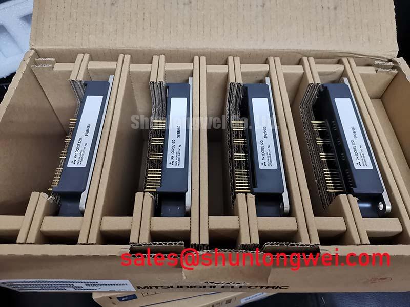

Technical Analysis of the R-Series Architecture
The PM100RSE120 leverages Mitsubishi’s 4th generation planar IGBT technology, which is specifically optimized for high-speed switching environments. One of the most critical parameters for this module is the $V_{CE(sat)}$ (Collector-Emitter Saturation Voltage), typically rated at 2.5V at $I_C = 100A$. This low saturation voltage minimizes conduction losses during the “on” state, which is vital for high-voltage industrial systems.
To explain the engineering significance of the module’s thermal management, consider this analogy: Think of the internal thermal resistance ($R_{th(j-c)}$) as the diameter of a high-pressure water pipe. A lower $R_{th(j-c)}$ value represents a wider pipe that allows heat to flow away from the semiconductor junctions much more easily. With an IGBT thermal resistance of 0.25 °C/W, the PM100RSE120 ensures that heat generated during high-frequency switching is efficiently moved to the baseplate, preventing localized hotspots that lead to premature failure.


Beyond raw power handling, the module excels in its integrated protection suite. It features dedicated sensors for Short-Circuit (SC), Over-Temperature (OT), and Under-Voltage Lockout (UV). When the device detects an SC event, it initiates a soft-shutdown within microseconds and pulls the fault output (Fo) pin low. This level of autonomy is a core part of the IPM advantage, as it protects the silicon even if the central MCU hangs or experiences latency.
Optimized Application Scenarios
The PM100RSE120 is a staple in the power semiconductors landscape for the following industrial environments:
- General Purpose Inverters (VFDs): Specifically designed for 400V class motor drives, where the integrated brake chopper manages regenerative energy during deceleration.
- Servo Amplifiers: The high-speed switching capability (up to 20kHz) allows for precise torque and position control with minimal audible noise.
- Uninterruptible Power Supplies (UPS): Efficient power conversion at 1200V levels ensures reliability for critical backup infrastructure.
- Renewable Energy Converters: Acts as the primary power stage for mid-sized solar or wind power inverters requiring high-voltage robustness.
Best Match: Systems requiring 3-phase inversion and dynamic braking in a compact footprint with autonomous protection against short-circuit and over-temperature faults.

Key Specifications and Ratings
| Parameter Category | Specific Parameter | Value (Unit) |
|---|---|---|
| Absolute Maximum Ratings | Collector-Emitter Voltage ($V_{CES}$) | 1200 V |
| Collector Current ($I_C$) | 100 A (at $T_C = 25^{circ}C$) | |
| Brake Collector Current ($I_C$) | 50 A | |
| Electrical Characteristics | $V_{CE(sat)}$ (Inverter) | 2.5 V (Typ.) |
| Short Circuit Trip Level | 200 A (Min.) | |
| Thermal/Mechanical | Junction Temperature ($T_j$) | -20 to +150 $^{circ}C$ |
| Isolation Voltage ($V_{iso}$) | 2500 Vrms (AC 1 min) |
Engineer FAQ
Q1: How do I handle the Fault Output (Fo) signal in the PM100RSE120?
A: The Fo pin is an open-collector output. You should connect it to the control supply voltage ($V_D$) via a pull-up resistor (typically 4.7kΩ). When a fault occurs, the module pulls this signal low, which should be used by the MCU to halt all PWM switching immediately.
Q2: What is the recommended switching frequency for this module?
A: While the PM100RSE120 is capable of higher speeds, it is optimized for switching frequencies up to 20kHz. Operating significantly beyond this frequency may increase switching losses ($P_{sw}$) and necessitate more aggressive thermal management solutions.
Q3: Can this module be used without the brake chopper?
A: Yes. If dynamic braking is not required for your application, the brake IGBT terminals (B, P) can be left open. However, the internal protection logic for the inverter stages remains fully operational.
The PM100RSE120 represents a sophisticated balance of power density and intelligence, providing a pre-validated environment for high-voltage motion control. By integrating the brake chopper and protective sensors, it empowers engineers to focus on system-level efficiency and control algorithms while ensuring the underlying silicon remains protected against the rigors of industrial electrical environments.