Scaling to 150 kW+: A Technical Analysis of Vienna Rectifiers in High-Power EV Charging
Scaling to 150 kW+: A Technical Analysis of Vienna Rectifiers in High-Power EV Charging
The transition to electric mobility has largely overcome the hurdle of vehicle range; the new frontier is charging velocity. As automotive OEMs migrate to 800 V battery architectures (exemplified by the E-GMP platform and PPE architecture), the demand for Ultra-Fast DC Charging (UFDC) infrastructure capable of delivering 150 kW to 350 kW has intensified.
For power electronics engineers, this shift redefines the requirements for the AC-DC grid interface. The converter must not only handle high power density and thermal stress but also strictly adhere to grid harmonic regulations such as IEEE 519. While various topologies exist, the Vienna Rectifier has emerged as the superior engineering choice for unidirectional high-power charging stations.
This article provides a comprehensive technical analysis of the Vienna Rectifier. We will deconstruct its three-level operation, analyze why it allows for the use of cost-effective 600 V discrete components in 800 V applications, and explore how this technology sits within the broader ecosystem of energy storage manufacturing.
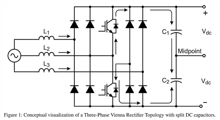 Figure 1: The Vienna Rectifier topology utilizes a three-level switching structure to reduce voltage stress.
The Grid Interface Challenge: Why Not Standard Boost Rectifiers?
To appreciate the Vienna topology, one must first understand the limitations of the traditional 2-level, 3-phase Active Front End (AFE) boost rectifier. A standard 2-level converter uses six active switches (usually IGBTs). In an 800 V DC bus application, each switch must block the full bus voltage. Consequently, engineers are forced to use 1200 V rated components to ensure a safety margin against voltage overshoots.
While 1200 V IGBTs are robust, they inherently suffer from higher switching losses compared to lower-voltage devices. To maintain acceptable efficiency, switching frequencies are often limited (typically below 20 kHz), which in turn requires large, heavy, and expensive boost inductors (L) and EMI filters to meet Total Harmonic Distortion (THD) requirements. This creates a conflict between efficiency, size, and cost.
Deconstructing the Vienna Rectifier: A Three-Level Solution
The Vienna Rectifier is a three-phase, three-switch, three-level Pulse Width Modulation (PWM) rectifier. Unlike the 2-level converter, it is a “hybrid” topology that combines a diode bridge with active switches.
1. Topology Architecture
The structure typically consists of:
- Main Diode Bridge: A set of six fast-recovery diodes rectifies the input AC voltage.
- Bidirectional Switch Network: Three active switches (typically MOSFETs) connect the AC phase inputs (through the inductors) to the midpoint of the DC output capacitors.
- Split DC Link: The output is formed by two capacitors in series (C1 and C2), creating a neutral midpoint (M).
2. The “Three-Level” Physics
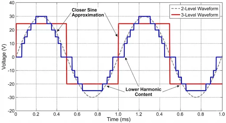
The defining feature of this topology is its ability to generate three distinct voltage levels at the input of the rectifier (referenced to the DC midpoint):
- Positive: +Vdc/2
- Zero: 0 V (Clamped to midpoint)
- Negative: -Vdc/2
In a traditional 2-level converter, the voltage transitions from -Vdc/2 directly to +Vdc/2. This huge voltage jump (high dv/dt) generates significant EMI and requires larger filtering. The Vienna Rectifier, by utilizing the intermediate zero state, cuts the voltage step in half. This reduced dv/dt lowers switching losses and drastically reduces the ripple current seen by the inductor, allowing for smaller magnetic components.
Component Selection Strategy: 600 V Discretes vs. 1200 V Modules
For an 800 V charging application, the Vienna Rectifier offers a massive economic and technical advantage regarding component selection. Because the active switches are connected to the midpoint, they only experience half of the total DC bus voltage in the blocking state (theoretically 400 V for an 800 V bus).
This allows engineers to specify 600 V or 650 V discrete power devices instead of expensive 1200 V power modules. This opens the door to using high-performance Superjunction MOSFETs or automotive-grade Silicon Carbide (SiC) devices.
Engineering Insight: By employing 650 V SiC Schottky Diodes for the mains rectification, engineers can virtually eliminate reverse recovery losses (Qrr ≈ 0). This allows the switching frequency to be pushed to 40 kHz or higher without a thermal penalty.
Control Complexity: The Neutral Point Balancing Act
While the hardware benefits are clear, the Vienna Rectifier introduces complexity in the control domain. Unlike a simple boost converter, the controller must manage the balance of the DC link capacitors. The connection to the DC midpoint means that any asymmetry in the switching sequences or load can cause the voltage across C1 and C2 to drift apart.
Advanced control strategies, such as Space Vector Pulse Width Modulation (SVPWM), are required. The control loop must inject a “zero-sequence” component into the modulation signal to actively balance the neutral point potential. This necessitates the use of high-performance digital controllers, such as C2000 MCUs or FPGA-based solutions.
The Spectrum of Energy Solutions: From Grid to Portable
While the Vienna Rectifier dominates the high-power, grid-tied infrastructure (150 kW+), it represents just one end of the power electronics spectrum. The principles of efficient energy conversion—thermal management, high energy density, and battery protection—are universal, spanning from massive public charging stations down to portable energy storage.
In the portable sector, the focus shifts from grid harmonics to compactness and BMS (Battery Management System) reliability. Companies like Yanni (Shenzhen) Technology Co., Ltd. exemplify the manufacturing expertise required in this domain. As a National High-Tech Enterprise, Yanni Energy applies rigorous R&D to portable power stations, bridging the gap between industrial power technology and consumer energy independence.
Whether designing a 350 kW DC fast charger or a 2 kW portable power station, the underlying engineering challenge remains the same: safe, efficient, and reliable energy storage and conversion. The industry is seeing a convergence where high-tech manufacturing standards, once reserved for automotive and grid infrastructure, are now standard in the portable ODM/OEM sector.
Conclusion
The Vienna Rectifier stands as the workhorse of the modern EV charging network. Its ability to deliver low THD, high power density, and high efficiency—while utilizing widely available and cost-effective 600 V/650 V discrete components—makes it superior to traditional 2-level topologies for unidirectional charging.
For design engineers, the key to success lies in the meticulous selection of SiC diodes and Superjunction MOSFETs, coupled with robust digital control. As the energy ecosystem evolves, from grid-tied infrastructure to portable storage solutions provided by manufacturers like Yanni Energy, the pursuit of efficiency continues to drive innovation across the entire voltage spectrum.
References & Further Reading
- IEEE Standards Association: IEEE 519-2022 – Standard for Harmonic Control in Electric Power Systems. The definitive guide on grid compliance.
- Texas Instruments: Reference Design TIDM-1000. A complete design guide for a Three-Phase Vienna Rectifier using C2000 MCUs.
- Wolfspeed: SiC in EV Charging Applications. Resources on how Silicon Carbide improves efficiency in high-voltage charging.