Technical Analysis of the FF150R12KS4 IGBT for High-Frequency Applications
Technical Analysis of the FF150R12KS4 IGBT Module
Introduction to the FF150R12KS4 for High-Frequency Power Systems
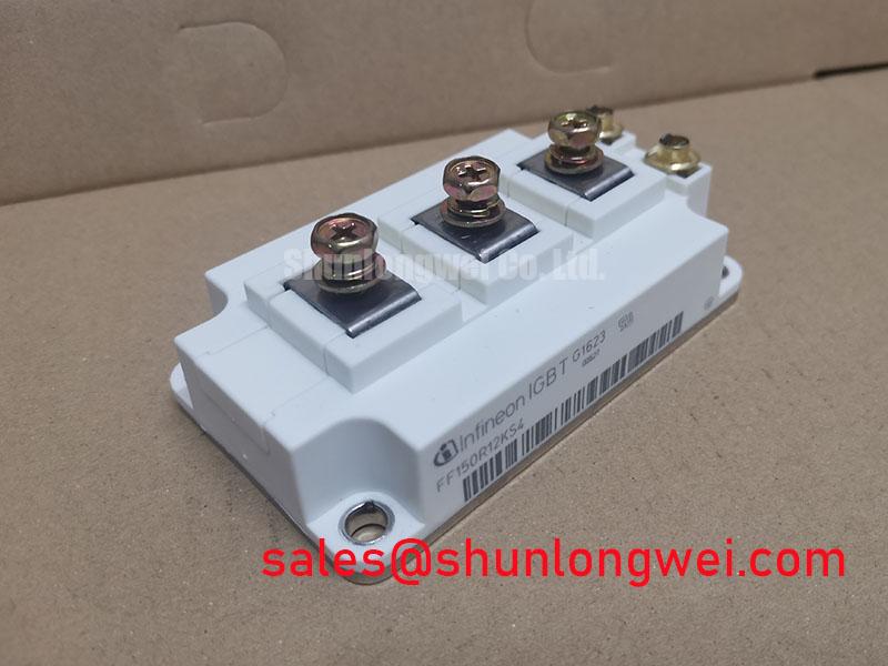
The FF150R12KS4 is a 1200V half-bridge IGBT module from Infineon, engineered for efficiency and reliability in high-frequency switching applications. This module’s primary value proposition is its balanced performance, combining low conduction and switching losses with robust thermal management capabilities, facilitated by the fast TrenchStop™ IGBT2 technology and an integrated NTC thermistor.
* **Core Specifications**: 1200V | 150A | VCE(sat) (typ) 2.15V
* **Key Advantages**: Low switching losses for higher frequency operation, integrated temperature monitoring for enhanced system safety.
* It directly addresses the need for efficient power conversion in systems where both power density and operational reliability are paramount.
Download the Official Datasheet (PDF)
Engineered for Balanced Loss Performance
A critical aspect of power module selection is the trade-off between conduction losses (heat generated when the device is on) and switching losses (heat generated during turn-on and turn-off transitions). The FF150R12KS4 utilizes a fast IGBT2 chip technology, which is optimized for lower switching losses (Eon and Eoff). This allows system designers to operate at higher switching frequencies, which in turn enables the use of smaller and lighter magnetic components, increasing the overall power density of the final system.
The collector-emitter saturation voltage (VCE(sat)) is a direct measure of conduction loss. The FF150R12KS4 specifies a typical VCE(sat) of 2.15V at its nominal current. While not the lowest in the market, this value is part of a deliberate design trade-off that favors reduced switching energy. This balance makes the module highly effective in applications like resonant inverters and high-frequency solar inverters, where performance at higher frequencies is a key requirement.

Another crucial parameter is the thermal resistance from junction to case (RthJC). Think of thermal resistance as the width of a pipe for heat; a lower value means heat can escape more easily from the active silicon chip to the heatsink. The datasheet specifies distinct RthJC values for the IGBT and the diode, allowing for precise thermal calculations. Effective thermal management is essential for leveraging the module’s full current-carrying capability and ensuring long-term operational reliability.
Optimized Application Scenarios
The specific characteristics of the FF150R12KS4 make it a strong candidate for several demanding applications:
- Motor Drives: Its fast switching capability allows for higher PWM frequencies, reducing motor noise and improving control accuracy in industrial automation and servo drives.
- Solar Inverters: The balance of low switching losses and robust thermal performance is ideal for the high-frequency DC-AC conversion stages in solar power systems.
- Uninterruptible Power Supplies (UPS): In UPS systems, the module’s efficiency and reliability are critical for ensuring a stable and uninterrupted power source. The robust design supports the demanding load profiles.
- Medical Applications: For power supplies in medical equipment like MRI or CT scanners, the module’s controlled switching behavior helps minimize EMI, a critical requirement in sensitive environments.
This module is an optimal match for high-frequency power converters requiring a balance between switching efficiency and robust thermal performance.
Key Specifications of the FF150R12KS4
| Absolute Maximum Ratings (Tvj = 25°C unless otherwise specified) | |
|---|---|
| Collector-Emitter Voltage (VCES) | 1200 V |
| Continuous Collector Current (IC nom) | 150 A |
| Repetitive Peak Collector Current (ICRM) | 300 A |
| Gate-Emitter Voltage (VGES) | ±20 V |
| Electrical & Thermal Characteristics | |
| Collector-Emitter Saturation Voltage (VCEsat) (IC=150A, VGE=15V, Tvj=25°C) | 2.15 V (typ.) |
| Switching-on Energy (Eon) per pulse | 17.50 mJ (typ.) |
| Switching-off Energy (Eoff) per pulse | 17.00 mJ (typ.) |
| Thermal Resistance, Junction to Case (RthJC), per IGBT | 0.110 K/W (max) |
| Short Circuit Withstand Time (tpsc) (VGE ≤ 15V, VCC = 800V) | 10 µs |
Engineer’s Frequently Asked Questions
1. What are the primary considerations for the gate drive circuit for the FF150R12KS4?
According to the datasheet, the recommended gate-emitter voltage (VGE) is +15V for turn-on and typically between -8V and -15V for turn-off. A proper gate drive design must provide sufficient current to charge and discharge the input capacitance (Cies) quickly to minimize switching losses. An external gate resistor must be selected to balance switching speed against voltage overshoot and EMI.
2. How does the integrated NTC thermistor improve system design?
The built-in NTC thermistor allows for real-time monitoring of the module’s baseplate temperature. This data is critical for implementing over-temperature protection in the system’s control logic, preventing thermal runaway and enhancing the long-term reliability of the power converter.
3. Can FF150R12KS4 modules be operated in parallel for higher current?
Yes, paralleling is possible. The positive temperature coefficient of VCE(sat) helps in achieving thermal stability and balanced current sharing among parallel modules. However, designers must ensure symmetrical layout for the gate drive circuits and power connections to minimize stray inductance and ensure simultaneous switching.
Enabling Efficient and Compact Power Conversion
The FF150R12KS4 IGBT module provides a well-balanced set of characteristics for engineers developing high-frequency power conversion systems. Its optimization towards lower switching losses enables higher operational frequencies, contributing to smaller, more power-dense designs. The inclusion of an NTC thermistor and the module’s robust thermal characteristics provide the foundation for building reliable, high-performance systems for a range of industrial and medical applications.