Toshiba MG400Q2YS60A: A Technical Review of a High-Power Industrial IGBT Module
## Toshiba MG400Q2YS60A 1200V 400A IGBT Module
High-Current Performance for Industrial Power Conversion
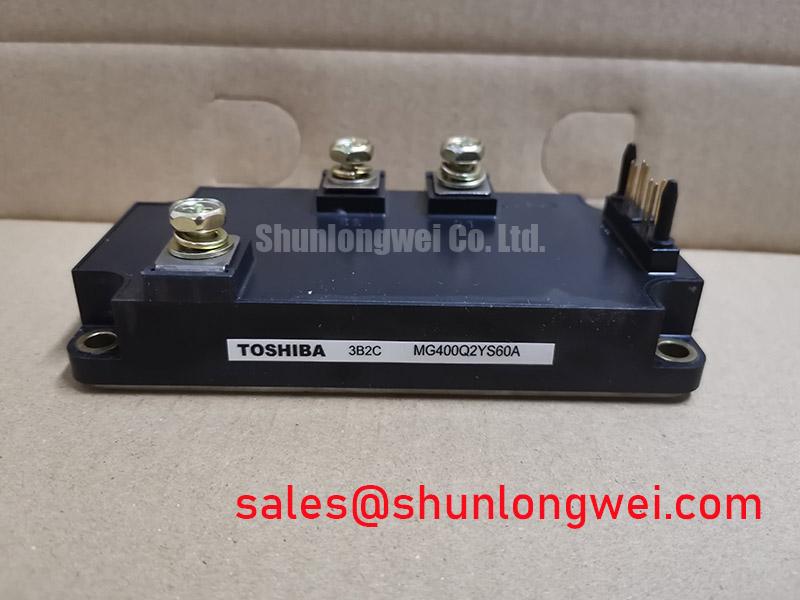
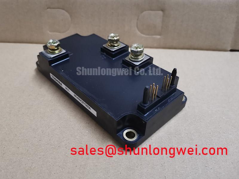
The Toshiba MG400Q2YS60A is a high-power dual IGBT module engineered for reliability in demanding industrial applications. It integrates two N-channel IGBTs in a half-bridge configuration, providing a robust solution for motor control and inverter systems. The module’s core value lies in its high current handling and rugged construction, featuring an isolated base that simplifies thermal management and enhances system safety. This design is focused on delivering consistent performance in high-stress environments where dependable power switching is critical.
* **Core Specifications**: 1200V | 400A | VCE(sat) 4.0V max
* **Key Advantages**: High current capacity for powerful systems, isolated baseplate simplifies heatsink mounting.
* **Engineering Focus**: The module’s Non-Punch-Through (NPT) IGBT technology provides inherent ruggedness, which is a significant factor for systems that experience high surge currents.
Download Official Datasheet (PDF)
Technical Analysis for System Design
The MG400Q2YS60A is built around a robust 1200V/400A specification, making it a suitable building block for three-phase inverters operating on 480V to 575V AC lines. Its NPT silicon structure offers a positive temperature coefficient for the collector-emitter saturation voltage (VCE(sat)). This characteristic naturally helps with current balancing when multiple IGBT modules are connected in parallel, a common practice in very high-power systems. Understanding this behavior is central to achieving a reliable parallel design, as discussed in guides on mastering high-power IGBT paralleling.
A critical aspect of power module integration is thermal management. The collector-emitter saturation voltage, with a maximum rating of 4.0V at 400A, is a primary contributor to conduction losses and, consequently, heat generation. The module’s ability to dissipate this heat is defined by its thermal resistance. You can think of thermal resistance (Rth(j-c)) as the diameter of a pipe; a lower value means a wider pipe, allowing heat to flow more easily away from the active silicon. The MG400Q2YS60A specifies a thermal resistance of 0.08°C/W per IGBT, enabling effective heat transfer to a heatsink and helping to keep the junction temperature within its safe operating limits of up to 150°C. Effective IGBT thermal design is fundamental to system longevity.
Optimized Application Scenarios
The electrical and thermal characteristics of the MG400Q2YS60A make it well-suited for several high-power industrial applications:
* **Industrial Motor Drives:** Its 400A continuous current rating allows for precise control of large three-phase AC induction motors in machinery such as pumps, fans, and conveyors.
* **Welding Power Supplies:** The module’s capacity to handle high pulse currents makes it a reliable component in inverter-based welding systems.
* **Uninterruptible Power Supplies (UPS):** The 1200V rating provides a necessary safety margin for battery-backed systems that protect critical infrastructure.
* **High-Power Inverters:** Suitable for use in central solar inverters or other renewable energy systems that require robust DC-AC power conversion.
This module is best matched for systems requiring durable, high-current switching at low-to-moderate frequencies where conduction losses are a primary design consideration.
Key Specifications of the MG400Q2YS60A
| Absolute Maximum Ratings | |
|---|---|
| Collector-Emitter Voltage (VCES) | 1200 V |
| Gate-Emitter Voltage (VGES) | ±20 V |
| Continuous Collector Current (IC) | 400 A |
| Peak Collector Current (ICP, 1ms pulse) | 800 A |
| Collector Power Dissipation (PC) | 2700 W |
| Operating Junction Temperature (Tj) | -40 to +150 °C |
| Isolation Voltage (Visol, AC 1 min.) | 2500 V |
| Electrical Characteristics (per IGBT) | |
| Collector-Emitter Saturation Voltage (VCE(sat)) @ IC=400A | 4.0 V max |
| Gate-Emitter Threshold Voltage (VGE(th)) | 4.0 to 8.0 V |
| Turn-On Time (ton) | 0.5 µs (typ.) |
| Turn-Off Time (toff) | 1.0 µs (typ.) |
| Diode Forward Voltage (VEC) @ IE=400A | 3.0 V max |
Engineer’s FAQ
What is the main advantage of the module’s isolated mounting base?
The isolated base, rated for 2500V AC for one minute, electrically separates the module’s internal power circuit from the heatsink it is mounted on. This simplifies the mechanical and thermal design by eliminating the need for external insulating materials, reducing assembly complexity and improving thermal transfer uniformity.
How can I estimate the conduction power loss for the MG400Q2YS60A in my application?
A first-order approximation for conduction loss per IGBT is calculated by the formula: P_cond ≈ VCE(sat) × I_out × D, where D is the duty cycle. To refine this calculation, you must consult the VCE(sat) vs. IC characteristic curves in the datasheet to find the specific saturation voltage at your operating current and estimated junction temperature.
What is a typical gate drive voltage for this IGBT module?
The datasheet specifies a gate-emitter threshold voltage (VGE(th)) range of 4.0V to 8.0V. To ensure the IGBT is fully turned on (saturated) and to achieve the lowest possible VCE(sat), a standard gate drive voltage of +15V is recommended for the on-state. A negative voltage is not strictly required for turn-off but can improve noise immunity.
Is the MG400Q2YS60A suitable for high-frequency applications like resonant converters?
With typical turn-on and turn-off times of 0.5 µs and 1.0 µs respectively, this module is optimized for low-to-medium frequency hard-switching applications (e.g., < 15 kHz). For higher frequencies, where switching losses become dominant, a module with faster switching characteristics would generally be a more efficient choice.
Enabling Robust High-Power Systems
The MG400Q2YS60A provides a proven, high-current switching foundation for engineers developing powerful and reliable industrial systems. Its straightforward design, combined with a thermally efficient package and rugged electrical characteristics, allows designers to focus on system-level performance while relying on a component built for demanding operational conditions. This module embodies a practical approach to high-power control.