Toshiba MG50Q2YS40 IGBT Module: A Technical Analysis for Power Conversion
Toshiba MG50Q2YS40 1200V 50A Dual IGBT Module Review
Technical Analysis of the MG50Q2YS40 IGBT Module
The Toshiba MG50Q2YS40 is a high-power switching module that integrates two Insulated Gate Bipolar Transistors (IGBTs) into a single, isolated package. This half-bridge configuration is engineered to provide a robust foundation for inverter and motor control systems, balancing voltage blocking capability with current handling capacity. It offers a streamlined solution for power conversion designs requiring efficient control of high-voltage loads.
- Core Specifications: 1200V | 50A | VCE(sat) 2.7V (max)
- Key Advantages: Integrated half-bridge circuit simplifies PCB layout and reduces parasitic inductance. The isolated mounting base streamlines thermal assembly.
- Design Focus: Intended for applications like AC and DC motor control and general-purpose inverters where reliability is paramount.
Download the Official MG50Q2YS40 Datasheet (PDF)
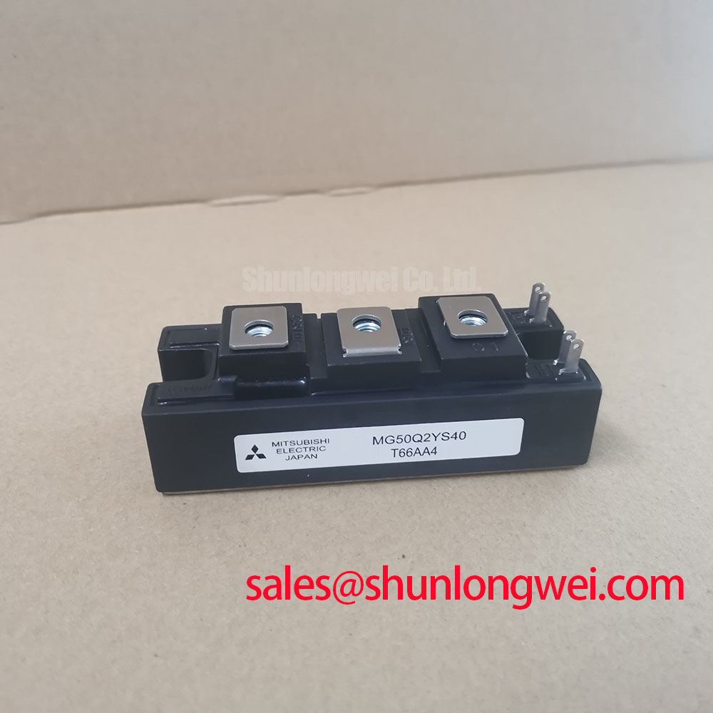
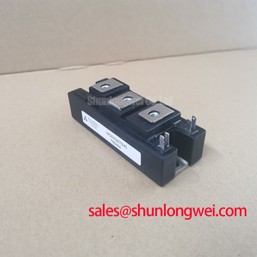
Technical Analysis for Power System Design
The MG50Q2YS40’s primary engineering value lies in its integrated dual-IGBT structure. By housing a complete half-bridge in one module, designers can minimize the physical loop area between the high-side and low-side switches. This inherently reduces stray inductance, a critical factor in mitigating voltage overshoots during high-speed switching events. The result is a more reliable circuit with potentially lower requirements for external snubber circuits.
A key parameter for thermal design is the collector-emitter saturation voltage, VCE(sat), which is specified at a maximum of 2.7V at 50A. This voltage can be thought of as a “voltage toll” paid each time current passes through the switch. A lower VCE(sat) means less power is converted into heat during the on-state. For the MG50Q2YS40, this value indicates a balance between conduction loss and the device’s high voltage-blocking capability. Effective thermal management, facilitated by its isolated baseplate, is essential to maintain junction temperatures within safe operating limits.
The module’s switching characteristics, including a typical turn-on time (ton) of 0.30 µs and a turn-off time (toff) of 0.40 µs, define its suitability for medium-frequency applications. These parameters are not optimized for ultra-high frequencies where switching losses would dominate, but they provide a dependable performance profile for motor drives and power supplies operating in the typical kilohertz range. The integrated free-wheeling diodes are matched to the IGBTs, ensuring a controlled path for inductive load currents and contributing to overall system robustness.
Optimized Application Scenarios
The specifications of the MG50Q2YS40 make it a strong candidate for several power conversion applications:
- AC Motor Control: Its 1200V rating provides a significant safety margin for 400/480V AC line applications, while the 50A current handling is sufficient for small to medium-sized industrial motors.
- UPS Systems: The integrated half-bridge simplifies the construction of the main inverter stage in an uninterruptible power supply, where reliability is a primary requirement.
- Welding Power Supplies: The module’s robust electrical and thermal characteristics can withstand the demanding pulsed-load conditions found in welding equipment.
- Switching Mode Power Supplies (SMPS): Suitable for high-power DC-DC converters and other SMPS topologies that require high voltage blocking and moderate switching speeds.
This module is best matched for systems requiring a reliable, integrated 1200V half-bridge solution for switching frequencies up to approximately 20 kHz.
Key Specifications of the MG50Q2YS40
| Absolute Maximum Ratings (Ta=25°C) | |
|---|---|
| Collector-Emitter Voltage (Vces) | 1200V |
| Gate-Emitter Voltage (Vges) | ±20V |
| DC Collector Current (Ic) | 50A |
| 1ms Pulse Collector Current (Icp) | 100A |
| Collector Power Dissipation (Pc) | 390W |
| Operating Junction Temperature (Tj) | 150°C |
| Electrical Characteristics (Ta=25°C) | |
| Collector-Emitter Saturation Voltage (Vce(sat)) | 2.7V (Max) @ Ic = 50A |
| Gate-Emitter Leakage Current (Iges) | ±500nA @ Vge = ±20V |
| Collector Cut-off Current (Ices) | 1mA @ Vce = 1200V |
| Diode Forward Voltage (Vf) | 2.5V (Max) @ Ie = 50A |
| Turn-On Time (ton) | 0.30µs (Typ) |
| Turn-Off Time (toff) | 0.40µs (Typ) |
Engineer’s FAQ
1. What is the impact of the 2.7V maximum VCE(sat) on thermal design?
A VCE(sat) of 2.7V at 50A means the module will dissipate 135W (P = V * I) per IGBT during conduction. This power loss must be managed by an appropriately sized heat sink. The datasheet specifies a junction-to-case thermal resistance of 0.32°C/W, which is a critical parameter for calculating the required heat sink performance to keep the junction temperature below the 150°C maximum.
2. What are the recommended mounting torque and thermal grease requirements?
According to the datasheet’s outline drawing, the module uses M5 mounting screws. While the datasheet doesn’t specify a torque value, a typical torque for an M5 screw in this type of application is between 2.5 and 4.0 N·m. It is crucial to use a thin, uniform layer of thermal compound to ensure minimal thermal resistance between the module’s baseplate and the heat sink. This is a key step in managing IGBT thermals.
3. Does this module include integrated freewheeling diodes?
Yes, the MG50Q2YS40 contains a co-packaged freewheeling diode (FWD) anti-parallel to each IGBT. This is evident from the internal equivalent circuit diagram in the datasheet. The FWDs are essential for providing a path for current from inductive loads, such as motor windings, during the IGBT’s off-state.
4. How does the isolated baseplate simplify installation?
The module features an electrically isolated baseplate with an isolation rating of 2500V (AC, 1 minute). This allows the module to be mounted directly to a grounded chassis or heat sink without the need for additional insulating layers like mica pads. This simplifies assembly, improves heat transfer compared to external insulation, and enhances overall system reliability.
Enabling Robust Power Conversion
The Toshiba MG50Q2YS40 provides a durable and functionally complete building block for power electronics engineers. Its integrated half-bridge design and well-defined electrical and thermal characteristics allow for the development of compact and reliable motor drives and inverters. By consolidating key components into a single isolated module, it helps simplify both the design process and the manufacturing assembly of the final system.