Toshiba MG75N2YS40: A Technical Analysis of a Robust Dual IGBT Module
## Toshiba MG75N2YS40 1200V 75A IGBT Module
Technical Analysis of a Robust Dual IGBT Module
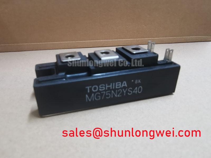
The Toshiba MG75N2YS40 is a 1200V, 75A N-channel dual IGBT module engineered for reliable performance in industrial power conversion systems. This device establishes a strong balance between conduction efficiency and thermal management, providing a durable building block for high-stress applications. It integrates two IGBTs with corresponding freewheeling diodes into a single, compact package. This half-bridge configuration simplifies system design compared to using discrete components.
* **Core Specifications**: 1200V | 75A | VCE(sat) of 2.7V (max)
* **Key Attributes**: Low conduction losses, effective thermal dissipation
* **Design Advantage**: The integrated 2-in-1 topology reduces stray inductance and streamlines assembly for inverter and chopper circuits.
Download Reference Datasheet (PDF)

Engineering Performance Analysis
A deep look into the MG75N2YS40’s datasheet reveals characteristics centered on operational stability and efficiency. Two key parameters highlight its engineering value: the collector-emitter saturation voltage (VCE(sat)) and the thermal resistance.
The VCE(sat) is specified at a maximum of 2.7V at the rated 75A collector current. This value is a direct indicator of the power lost as heat while the IGBT is conducting current. A lower VCE(sat) translates to reduced conduction losses, which improves overall system efficiency and lessens the thermal load on the cooling system. This is particularly important in applications with high duty cycles where the device spends significant time in the on-state.

Effective heat removal is governed by the module’s thermal resistance. The junction-to-case thermal resistance (Rth(j-c)) for the IGBT is documented at 0.26°C/W. This parameter can be visualized as the width of a pipe meant for heat to escape; a lower value indicates a wider, more effective pipe. This efficient thermal pathway allows heat generated at the semiconductor junction to transfer effectively to the heatsink, a critical factor for preventing overheating and ensuring long-term reliability under sustained loads. For more information on thermal design, see our guide to mastering IGBT thermal design.
Optimized Application Scenarios
The electrical and thermal characteristics of the MG75N2YS40 make it a suitable component for a range of medium-power industrial applications where durability is essential.
* **Variable Frequency Drives (VFDs)**: The 1200V blocking voltage provides a robust safety margin for motor drives operating on 400V or 480V AC lines, while its 75A current rating fits a wide array of industrial motor sizes.
* **Uninterruptible Power Supplies (UPS)**: In UPS inverters, the module’s low conduction losses contribute to higher system efficiency, and its proven package design ensures the high reliability required for backup power systems.
* **Welding Power Supplies**: The module’s thermally efficient packaging and wide Safe Operating Area (SOA) allow it to withstand the high-current, pulsed-load conditions characteristic of welding applications.
* **Solar Inverters**: Its voltage and current ratings are well-matched for the DC-AC conversion stage in string solar inverters, where efficiency and long-term reliability are key performance metrics.
This module is best matched for applications requiring a durable power switch with balanced losses rather than extremely high switching frequencies.
Key Specifications of the MG75N2YS40
| Absolute Maximum Ratings (Ta=25°C) | |
|---|---|
| Collector-Emitter Voltage (VCES) | 1200 V |
| Gate-Emitter Voltage (VGES) | ±20 V |
| Collector Current (DC) (IC) | 75 A |
| Collector Power Dissipation (PC) | 480 W |
| Operating Junction Temperature (Tj) | 150 °C |
| Electrical Characteristics (Ta=25°C) | |
| Collector-Emitter Saturation Voltage (VCE(sat)) (IC=75A, VGE=15V) | 2.7 V (Max) |
| Gate-Emitter Leakage Current (IGES) (VGE=±20V) | ±500 nA |
| Collector Cut-off Current (ICES) (VCE=1200V) | 1 mA |
| Forward Voltage (VECF) (IEC=75A) | 2.5 V (Max) |
| Thermal and Isolation Characteristics | |
| Thermal Resistance (Rth(j-c)) – IGBT | 0.26 °C/W |
| Thermal Resistance (Rth(j-c)) – Diode | 0.52 °C/W |
| Isolation Voltage (Visol) | 2500 V (AC, 1 minute) |
Note: These values are highlights. For comprehensive data, including dynamic characteristics and performance curves, refer to the official manufacturer datasheet.
Engineer’s Frequently Asked Questions
What are the recommended mounting procedures for the MG75N2YS40?
Proper mounting is crucial for effective thermal management. The module’s baseplate should be mounted to a heatsink using a thin, uniform layer of thermal interface material. The recommended mounting torque for the main terminals is 2.5 – 3.5 N·m, and for the mounting screws, it is also 2.5 – 3.5 N·m. Uneven or excessive torque can lead to poor thermal contact or damage the module’s isolated base.
How does the gate-emitter threshold voltage affect the design of the gate drive circuit?
The datasheet specifies a gate-emitter threshold voltage (VGE(th)) range of 5.0V to 8.0V. A gate drive circuit must provide a voltage significantly higher than the 8.0V maximum to ensure the IGBT is fully saturated (turned on) to achieve the low VCE(sat). Typically, a +15V drive voltage is used. The drive circuit must also be able to provide sufficient peak current to charge and discharge the input capacitance quickly, which is essential for managing switching performance.
Can the MG75N2YS40 be used in parallel to achieve higher current ratings?
While paralleling IGBT modules is possible, it requires careful engineering to ensure proper current sharing. Factors like VCE(sat) and VGE(th) matching, as well as symmetry in the gate drive layout and power busbar, are critical. Mismatches can cause one module to carry more current, leading to thermal runaway. For high-current designs, exploring a single, higher-rated module or reading about IGBT paralleling techniques is recommended.
The MG75N2YS40 provides a robust and reliable foundation for industrial power stages. Its design prioritizes durability and thermal stability, enabling engineers to build resilient systems that operate consistently under demanding electrical and thermal loads.