At the recent PCIM Europe 2023 conference, several silicon carbide device manufacturers and university researchers introduced and shared performance characteristics of SiC MOSFETs at the 3.3-kV voltage rating. This voltage is increasingly being seen as key to meeting several future applications, such as medium-voltage grid power conversion at a 1,500-V DC-link voltage, photovoltaics and wind renewable-energy converters, as well as traction inverters for electric rail. In this article, we will discuss the new 3.3-kV SiC MOSFET modules from Infineon Technologies that can make significant improvements in modern railway traction systems.
The railway traction system
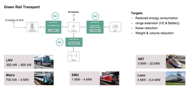
Figure 1 illustrates a simplified block schematic of the power-conversion requirements in an electric train application. The SiC devices find applications in the rectifiers needed to convert incoming AC power from overhead lines to the DC-link voltage, the inverters to convert this DC-link power to the motors and the DC/DC converters needed for auxiliary power systems and, in the case of hybrid propulsion trains, on-board batteries or hydrogen fuel cells. Some of the key requirements for this application are:
- High power density and energy efficiency, which ensure less cooling needs and greater transport capacity
- Long lifetime (>30 years) under a mission profile that requires frequent power-level changes from the acceleration and braking phases of the train
- Use of standardized power modules that are scalable for the various power levels highlighted in Figure 1
- Specifically for the SiC MOSFET used here, fast switching with low overshoots during transitions, as well as robust short-circuit protection and surge-current ruggedness to ensure that module safety specifications are met

The 3.3-kV CoolSiC MOSFET
The 3.3-kV CoolSiC MOSFET used in these power modules leverages the many years of experience that Infineon has in the lower-voltage class of CoolSiC MOSFETs. As shown in Figure 2a, these are trench MOSFETs that take advantage of the increased channel mobility along the favored A-plane (11-20). This improves the specific on-state resistance (RDS(on)) compared with a planar MOSFET device. A thicker gate oxide ensures good reliability.


As shown in Figure 2b, the JFET region of the 3.3-kV device needed to be optimized for RDS(on) improvements. This was done in conjunction with the optimization of the device capacitances and short-circuit withstand time (tsc). Simultaneous reductions in the device saturation current (Isat) and the ratio of the Miller gate-drain to gate-source capacitances (Cgd/Cgs) was possible through the tuning of the deep p-implant.2 The Isat reduction improves the tsc. A lower Cgd/Cgs ratio increases dV/dt transitions for lower switching losses while also minimizing overshoots seen on the gate and giving a greater margin for the prevention of parasitic turn-on of the device. The internal MOSFET body diode is used for commutation. Because a Schottky diode is not used in parallel, the overall MOSFET chip area could be optimized for the module’s current rating while also having a higher surge-current rating.
3.3-kV CoolSiC MOSFETs in XHP2 package with XT technology
The XHP2 power module package addresses voltage classes from 1.7 kV to 3.3 kV for both silicon IGBTs and SiC MOSFETs. This package optimizes the layout and design of the DC (±) terminals and bus bar for a low module stray inductance of Ls~10 nH.2 In a traction inverter application, the power-cycling requirements can create stress on the interconnections and limit module lifetime. The .XT technology, which was first implemented in Infineon’s IGBT modules,4 is used for the 3.3-kV CoolSiC devices housed in the XHP2 modules. As shown in Figure 3, the .XT features copper (Cu) front-side metallization on the SiC dies, along with heavy Cu bond wires. Thermal resistance is reduced, hence improving power cycling.


Some of the key features of the overall module are depicted in Figure 4. The FF2000UXTR33T2M1 is a 2-mΩ module rated for a nominal current of 1,000 A, while the FF2600XTR33T2M1 is a 2.6-mΩ module rated at 750 A. The package has an isolation rating (VISOL) of 6 kV and a stray inductance of Ls~10 nH.


Switching performance of the 3.3-kV XHP2 modules
Figure 4 shows the switching performance of the module at 25°C and 150°C under nominal operating conditions of IDS = 1,000 A, VDS = 1,800 V, VGS = 15 V/–5 V and Ls = 30 nH. Turn-on di/dt = 7 kA/µs and turn-off dV/dt = 17.5 kV/µs were measured with the gate-resistor selection used to ensure safe switching characteristics.


To evaluate the increase in power density, the 3.3-kV CoolSiC in XHP2 was compared with a 3.3-kV IGBT module with the same module footprint of 140 × 100 mm (FF450R33T3E3). The simulation results shown in Figure 6(a) were done at a DC-link voltage of 1,800 V and an operational junction temperature of Tvj = 125°C. It shows that at a 4-kHz switching frequency, the SiC module produced a 7.3× higher Irms value (Irms_2 in Figure 6), compared with the Irms_1 value produced by the silicon IGBT.

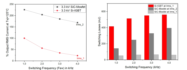
Comparing the switching losses, at 4 kHz, the IGBT produced 561 mJ of loss, even though its Irms current was much lower, compared with the loss of 395 mJ from the SiC MOSFET. If the SiC MOSFET were to be run at the lower Irms value of the IGBT, its losses would be 9.3× lower than that of the IGBT. Lowering dead times during synchronous rectification in the converter can further reduce the reverse-recovery losses, especially at high temperatures, hence reducing turn-on losses. For example, using a 1-µs dead time compared with 5 µs can increase the Irms current output by as much as 12% at a switching frequency of 10 kHz.
Field trial results of the 3.3-kV CoolSiC XHP2 module for railway traction
A joint field trial was conducted in 2022 by Siemens Mobility and Stadtwerke München (SWM) on a streetcar in Munich that was equipped with the 3.3-kV CoolSiC XHP2 power modules for the traction inverter. This test was done for a period of one year, covering a total of 65,000 km. The results from these tests showed a 10% improvement in energy efficiency, as shown in Figure 7. The weight and volume reduction of the converter and traction system are between 10% and 25%.7 Because less heat needs to be dissipated with SiC, smaller heat exchangers could be used at lower airflow rates, helping improve the aerodynamic drag on the train. One of the improvements from a passenger comfort point of view is the much quieter ride enabled by SiC. This comes from the combination of the higher switching frequency in the traction converter and smaller heat-exchange units. Trains that operate on a hybrid propulsion system (such as using batteries or hydrogen fuel cells for the energy source) for some parts of the track that do not have the AC input power lines (i.e., catenary-free) will benefit from the SiC-based traction inverter due to the advantages mentioned above. This can translate to extended catenary-free mileage.


Source: https://www.slw-ele.com/3-3-kv-sic-mosfets-promise-a-more-efficient-and-quieter-train-ride.html