PS21353-G Technical Review: Mitsubishi’s 600V 10A Intelligent Power Module
PS21353-G | 600V 10A DIP-IPM Inverter Module by Mitsubishi
Introduction to the PS21353-G Intelligent Power Module
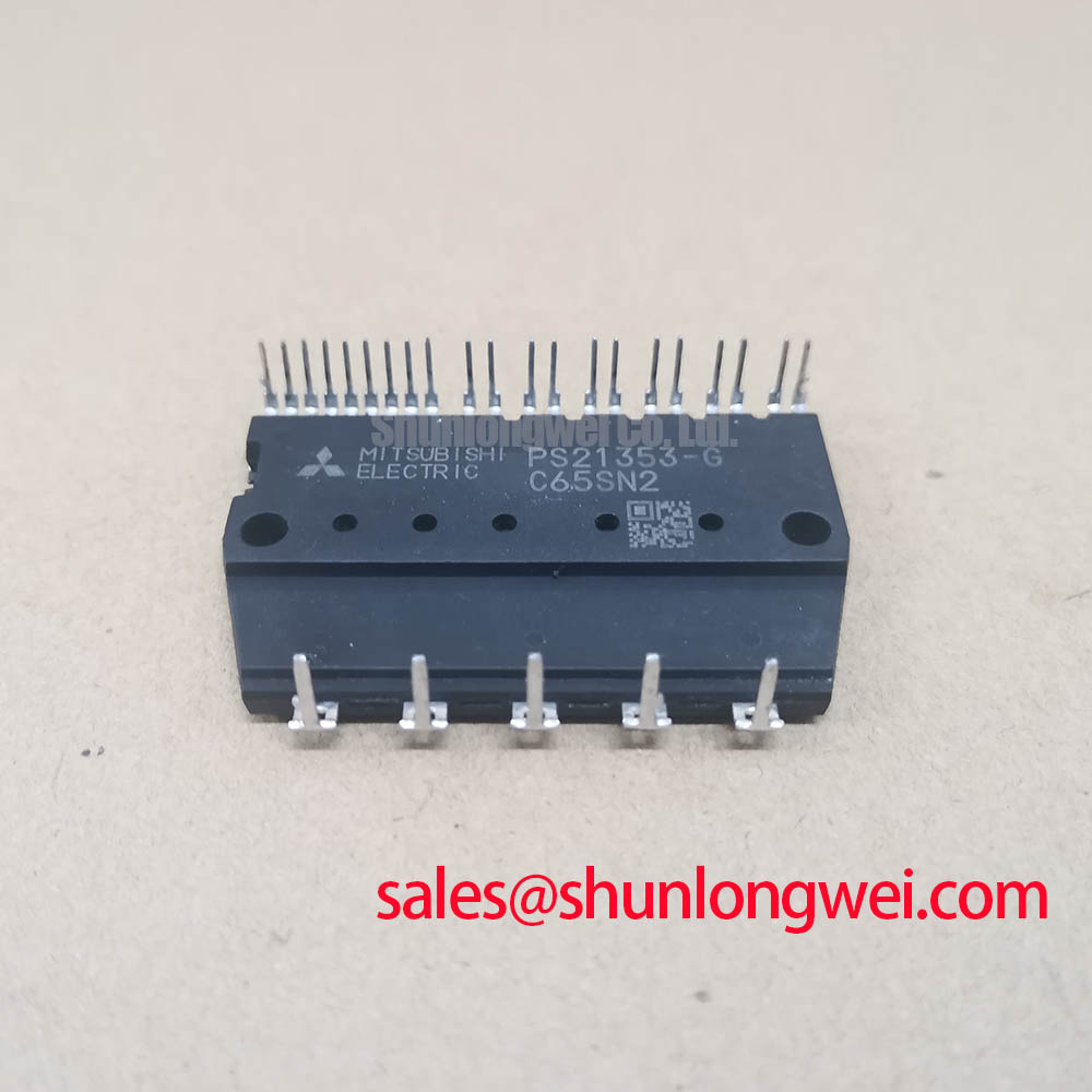
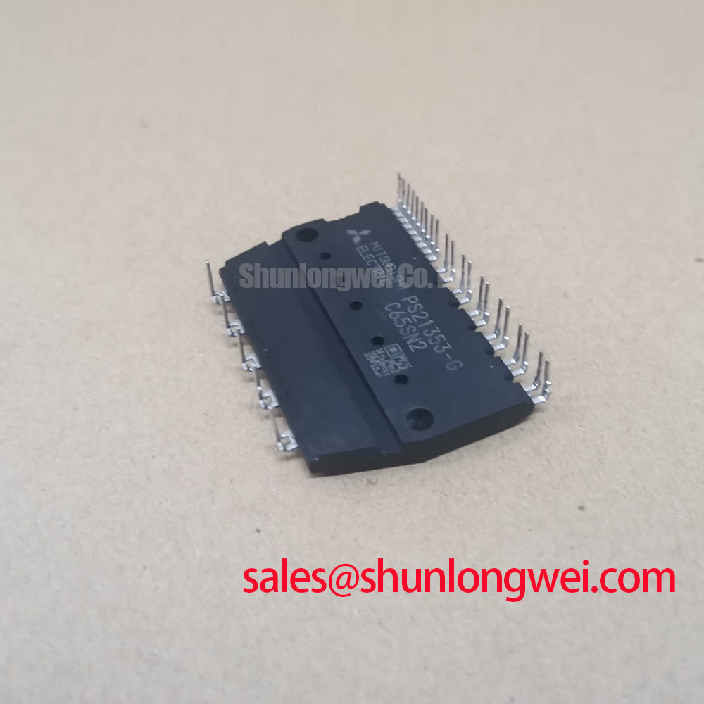
The Mitsubishi PS21353-G is a DIP Intelligent Power Module (IPM) that integrates a three-phase IGBT inverter, gate drivers, and protection circuits into a single compact package. This high level of integration provides a streamlined solution for controlling low-power motors, significantly reducing PCB space and design complexity. By incorporating built-in bootstrap diodes with current-limiting resistors, the module further simplifies the power supply design for the high-side gate drivers.
- Core Specifications: 600V | 10A | 3-Phase IGBT Inverter
- Key Advantages: Reduces component count, enhances system reliability with integrated protection.
- Design Simplification: Allows direct drive from 3.3V/5V microcontrollers without optocouplers.
Download the Official Datasheet (PDF)
Technical Analysis: Integration and Protection
A significant engineering benefit of the PS21353-G IPM is its comprehensive suite of built-in protection features. The module includes circuitry for short-circuit (SC) protection for the low-side IGBTs, control supply under-voltage (UV) lockout, and over-temperature (OT) protection. These integrated safeguards enhance the overall robustness of the motor drive system, reduce external component count, and simplify the certification process. The fault signal (FO) output pin provides a clear, logic-level diagnostic signal to the system’s microcontroller in the event of an SC or UV fault, enabling safe shutdown procedures.
The under-voltage lockout function is critical for system reliability. Think of it as a safety check on a power tool; it prevents the module from operating with insufficient control voltage, which could lead to unpredictable IGBT switching, increased thermal stress, and potential device failure. By ensuring the gate drive voltage is always within the specified safe operating range, the UV protection helps prevent catastrophic damage. This feature is essential for applications where power supply stability cannot always be guaranteed. For more insight on this topic, see our guide to the critical role of under-voltage lockout.
Optimized Application Scenarios
The specific characteristics of the PS21353-G make it a strong candidate for several low-power motor control applications. Its performance is optimized for systems using a PWM frequency around 15 kHz.
- Home Appliances: Ideal for driving motors in washing machines, refrigerators, and air conditioner fans where compact size, high reliability, and thermal efficiency are primary requirements.
- Small Industrial Pumps and Fans: The module’s 600V/10A rating and integrated protection are well-suited for fractional horsepower motors used in industrial automation.
- Small Servo Motors: Direct connection to a CPU or MCU simplifies the control architecture in small-scale robotics and automated machinery.
Its all-in-one design is an excellent match for cost-sensitive, high-volume home appliance and light industrial motor control where design simplicity is paramount.

Key Specification Parameters for PS21353-G
The following data is extracted from the official manufacturer’s datasheet. It is intended for reference and should be verified with the full PDF document.
| Parameter | Symbol | Conditions | Value | Unit |
|---|---|---|---|---|
| Absolute Maximum Ratings | ||||
| Supply Voltage | VCC | Applied between P-N1 | 450 | V |
| Collector-Emitter Voltage | VCES | – | 600 | V |
| Each IGBT Collector Current | ±IC | TC = 25°C | 10 | A |
| Each IGBT Collector Current (Peak) | ±ICP | TC = 25°C, less than 1ms | 20 | A |
| Collector Dissipation | PC | TC = 25°C, per 1 chip | 25 | W |
| Junction Temperature | Tj | – | -20 to +125 | °C |
| Electrical Characteristics | ||||
| Collector-Emitter Saturation Voltage | VCE(sat) | IC = 10A, VD = 15V | 2.0 (Typ) / 2.5 (Max) | V |
| Short Circuit Trip Level | SC | VCC=300V, VD=15V, Tj=125°C | 20 (Typ) | A |
Engineer’s FAQ
- What are the bootstrap circuit requirements for the PS21353-G?
- The PS21353-G integrates high-speed bootstrap diodes and current-limiting resistors, simplifying the design. An external bootstrap capacitor is required for each high-side driver. The datasheet recommends a tight tolerance, temperature-compensated electrolytic capacitor, with a value dependent on the PWM control scheme. For additional details, refer to the application circuit examples in the official datasheet.
- How should this IPM be mounted for effective thermal management?
- For proper heat dissipation, the module should be mounted on a heatsink. Apply a layer of thermal grease (100-200µm) evenly on the contact surface. Ensure the heatsink has a flatness between -50µm and +100µm. Use the specified mounting screw torque to guarantee good thermal contact without inducing mechanical stress on the package.
- What is the function of the VFO pin?
- The VFO (Fault Output) pin is an open-collector output that signals a fault condition. It goes to a low state when a short-circuit (SC) is detected on the N-side IGBTs or when the control supply voltage drops below the under-voltage (UV) threshold. This pin should be pulled up to the 5V logic supply through a resistor (e.g., 5.1 kΩ).
- What is the maximum recommended PWM frequency?
- The datasheet indicates the module is optimized for operation with a PWM frequency up to 20kHz.


System Design Enablement
The PS21353-G provides engineers with a highly integrated and protected power stage for AC 100-200V class inverter drives. Its single-package solution accelerates development time, reduces BOM costs, and enhances the reliability of the end product. By leveraging the integrated drivers and protection functions, design teams can focus on system-level control and performance optimization, delivering compact and robust motor control solutions to the market more efficiently. Explore further resources like our analysis of PIM vs. Discrete IGBTs for more context on strategic component selection.