CM100DY-24NF IGBT Module: A Technical Analysis for High-Efficiency Power Conversion
## Mitsubishi CM100DY-24NF: 1200V 100A Dual IGBT Module
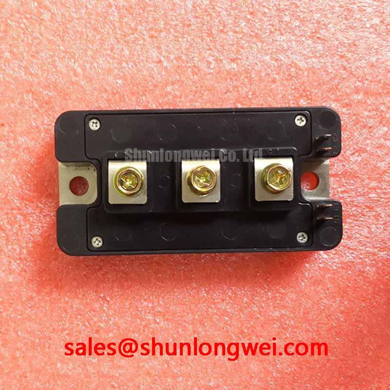
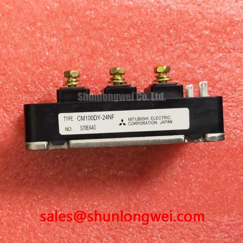
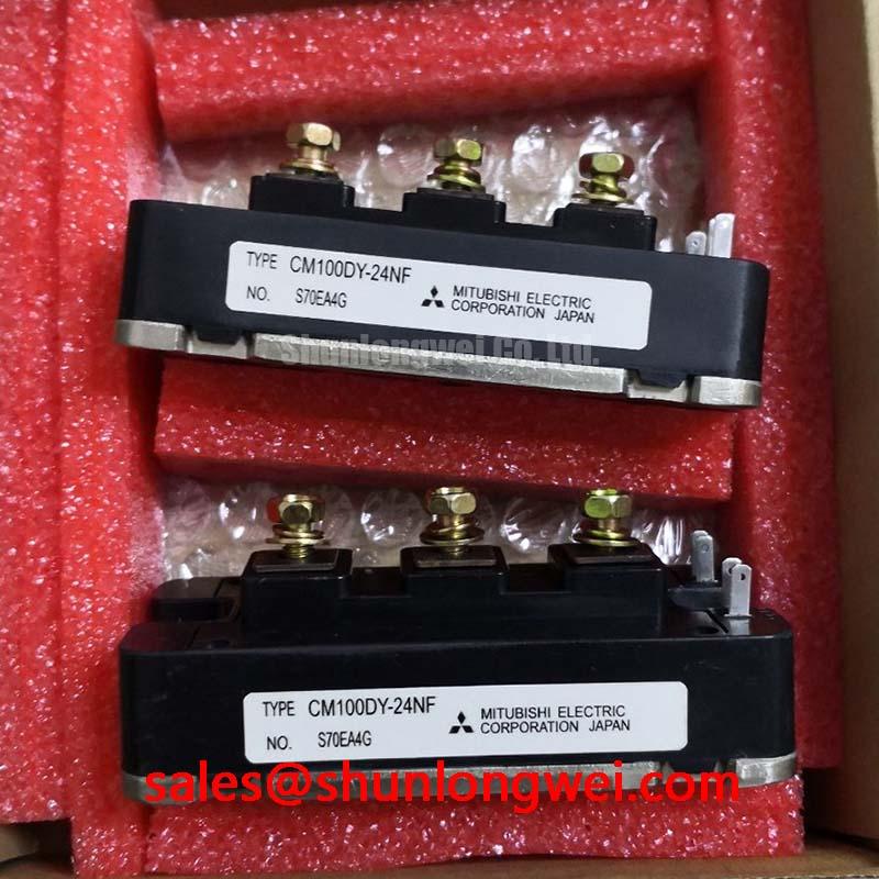
The Mitsubishi CM100DY-24NF is a dual IGBT module from the NF-Series, engineered for high-power switching applications. It integrates two IGBTs in a half-bridge configuration, providing a robust solution for power conversion systems that demand efficiency and reliability. This module is characterized by a favorable balance between conduction and switching losses, making it a strong candidate for systems like motor drives and uninterruptible power supplies.
* **Core Specifications**: 1200V | 100A | VCE(sat) (typ): 2.2V
* **Key Advantages**: Low collector-emitter saturation voltage for reduced static power loss and an integrated super-fast recovery free-wheel diode for optimized switching behavior.
* **Design Consideration**: The module’s electrically isolated baseplate simplifies thermal management by allowing direct mounting to a heatsink, which reduces both assembly complexity and overall thermal resistance.
Download the Official CM100DY-24NF Datasheet (PDF)

Technical Analysis for System Integration
The engineering value of the CM100DY-24NF is centered on its electrical and thermal efficiency. The collector-emitter saturation voltage, `VCE(sat)`, has a typical value of 2.2V at the nominal current of 100A. This parameter is crucial as it directly impacts conduction losses. You can think of `VCE(sat)` as a small voltage drop that occurs when the switch is fully on; a lower value means less power is converted into waste heat. This efficiency gain reduces the load on the cooling system and can lead to a more compact and cost-effective thermal design.
Another key feature is the module’s construction. The CM100DY-24NF features an electrically isolated baseplate, rated for 2500V (AC, for 1 minute). This design eliminates the need for external insulating materials between the module and the heatsink. By creating a direct thermal path, this feature lowers the junction-to-case thermal resistance `Rth(j-c)`, specified at 0.16°C/W per IGBT. Effective heat dissipation is a primary factor in the long-term reliability of power semiconductors, and this integrated isolation simplifies achieving it.
Optimized Application Scenarios
The characteristics of the CM100DY-24NF make it suitable for a range of medium-to-high power applications.
* **AC Motor Control & VFDs**: The 100A continuous current rating provides sufficient capacity for controlling medium-sized industrial motors, while the integrated free-wheeling diodes manage the inductive load currents during switching.
* **Uninterruptible Power Supplies (UPS)**: The module’s 1200V blocking voltage offers a solid safety margin for systems connected to 400/480V AC lines, and its low conduction losses improve battery runtime and overall efficiency.
* **Servo Drives**: Fast and clean switching characteristics, supported by the super-fast recovery diode, are essential for the precise current control required in servo applications.
For power conversion systems requiring a dependable balance of performance, thermal efficiency, and robust construction, this module presents a technically sound component choice.
Key Specifications of the CM100DY-24NF
| Absolute Maximum Ratings (Tj = 25°C) | ||
|---|---|---|
| Collector-Emitter Voltage | VCES | 1200V |
| Gate-Emitter Voltage | VGES | ±20V |
| Collector Current (DC) | IC | 100A |
| Peak Collector Current | ICM | 200A |
| Maximum Collector Dissipation | PC | 520W |
| Junction Temperature | Tj | -40 to +150°C |
| Electrical Characteristics (Tj = 25°C) | ||
| Collector-Emitter Saturation Voltage | VCE(sat) | 2.2V (typ) / 2.7V (max) @ IC=100A |
| Gate-Emitter Threshold Voltage | VGE(th) | 5.5V to 8.5V |
| Turn-On Time | ton | 300ns (typ) |
| Turn-Off Time | toff | 350ns (typ) |
*All parameters are sourced directly from the official manufacturer’s datasheet.
Engineer’s FAQ
1. What are the gate drive requirements for the CM100DY-24NF?
The recommended gate-emitter voltage (VGE) is +15V for turn-on and -10V to -15V for turn-off. The gate-emitter threshold voltage VGE(th) is between 5.5V and 8.5V. A robust gate drive circuit that can supply these voltages with appropriate peak current is necessary for achieving the specified switching times and minimizing losses.
2. What is the correct mounting procedure to ensure proper thermal contact?
To achieve optimal heat transfer, the heatsink surface should be flat and clean. The datasheet specifies applying a thermal compound layer of approximately 100-150µm. Use the M5 mounting screws and tighten them to the recommended torque of 3.0-4.0 N·m. Uneven or excessive torque can warp the baseplate, increasing thermal resistance and potentially damaging the module.
3. How does the internal free-wheeling diode (FWD) affect performance?
The CM100DY-24NF includes a super-fast recovery FWD matched to the IGBT. This diode provides a path for inductive motor current when the IGBT is turned off. Its low forward voltage drop (VEC) and fast reverse recovery time (trr) are critical for reducing power loss during commutation, which is especially important in high-frequency inverter applications.
4. Is it possible to parallel these modules for higher current capacity?
While paralleling IGBT modules is a common practice, it requires careful design to ensure proper current sharing. Factors like a positive temperature coefficient of VCE(sat) and tight VGE(th) matching are important. For a deeper understanding of the challenges, refer to resources on IGBT paralleling and gate drive design.
Enabling Efficient Power Conversion
The CM100DY-24NF IGBT module provides a well-documented, high-performance solution for power electronics engineers. Its combination of low conduction losses, integrated protection features, and a thermally efficient package allows for the design of compact and reliable power conversion systems. By adhering to the specifications in the datasheet, designers can leverage this module to achieve their system-level performance goals.