Fuji 7MBR150VN120-50: A Technical Review of the High-Integration 7-in-1 IGBT Module
Fuji 7MBR150VN120-50: 1200V 150A 7-in-1 IGBT Module
Integrated Power Solution for Demanding Inverter Designs
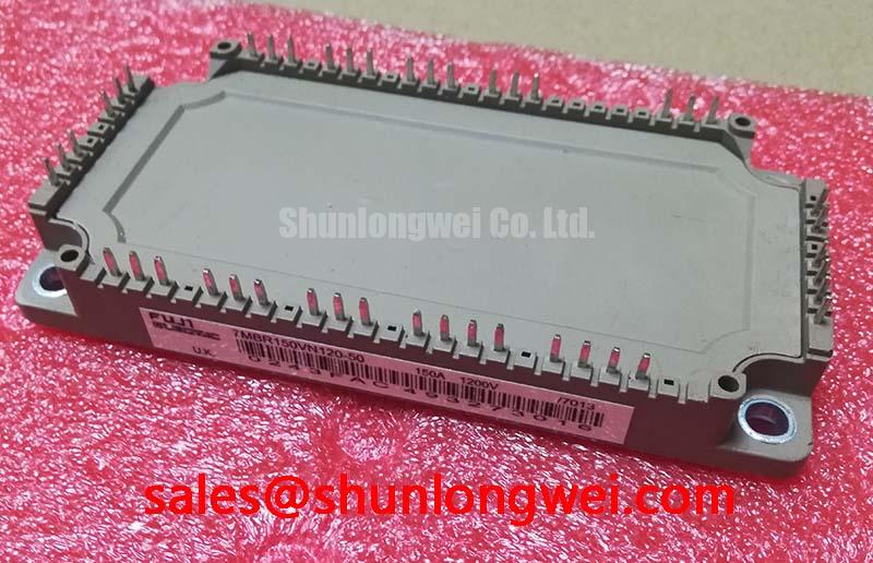
The Fuji Electric 7MBR150VN120-50 is a V-Series Power Integrated Module (PIM) that consolidates a three-phase converter, a three-phase inverter, and a dynamic brake chopper into a single compact package. This high level of integration provides a streamlined solution for engineers developing motor drives and power supplies, aiming to reduce system size, assembly complexity, and overall cost while enhancing reliability.
- Core Specifications: 1200V | 150A (Inverter) | VCE(sat) (typ) 2.45V
- Key Advantages: High-integration PIM design minimizes stray inductance; incorporates low-loss V-Series IGBT technology.
- Built-in Monitoring: An integrated NTC thermistor enables direct monitoring of module temperature, facilitating robust over-temperature protection.
Download Official Datasheet (PDF)

Technical Analysis of the 7-in-1 Architecture
The primary engineering value of the 7MBR150VN120-50 lies in its integrated architecture. Combining seven power stages (three-phase rectifier, brake chopper, and three-phase inverter) into one module drastically reduces the physical footprint and component count compared to discrete solutions. This consolidation simplifies the power stage layout, reduces parasitic inductance, and mitigates EMI challenges. By minimizing the number of soldered connections, the architecture enhances the overall reliability of the power system, a concept further explored in our analysis of PIM vs. discrete IGBT strategies.
At the core of the module is Fuji Electric’s V-Series IGBT technology, engineered for a balance between conduction and switching losses. The collector-emitter saturation voltage (VCE(sat)) is a critical parameter for efficiency. A lower VCE(sat) directly reduces the heat generated during the on-state. The thermal resistance from junction to case (Rth(j-c)) dictates how effectively this heat is transferred away from the semiconductor. Think of thermal resistance as the width of a pipe; a lower value, like that of the 7MBR150VN120-50, signifies a wider pipe, allowing heat to flow away more easily and keeping the junction temperature within safe limits. This efficiency is paramount for achieving long-term system reliability, a topic covered in discussions on IGBT reliability and power cycling.
Optimized Application Scenarios
The specific feature set of this module makes it a strong candidate for several power conversion applications:
- Inverters for Motor Drives: The all-in-one CIB (Converter-Inverter-Brake) topology is purpose-built for three-phase motor drive applications, simplifying manufacturing and reducing inventory.
- AC and DC Servo Drive Amplifiers: Its compact footprint and integrated nature allow for the design of smaller, more power-dense servo amplifiers where space is a premium.
- Uninterruptible Power Supplies (UPS): The integrated converter and inverter stages are well-suited for online UPS systems, where the module’s high reliability contributes to system uptime.
This module is best matched for power conversion systems requiring a compact, highly integrated solution with robust thermal performance for medium-power industrial applications.
Key Specifications of the 7MBR150VN120-50
| Absolute Maximum Ratings (Tc=25°C) | ||
|---|---|---|
| Parameter | Inverter / Brake Part | Converter Part |
| Collector-Emitter Voltage (VCES) | 1200 V | – |
| Gate-Emitter Voltage (VGES) | ±20 V | – |
| Continuous Collector Current (Ic) | 150A (Inv, Tc=100°C) / 100A (Brake, Tc=80°C) | – |
| Repetitive Peak Reverse Voltage (VRRM) | 1200 V (Diode) | 1600 V |
| Average Output Current (Io) | – | 150 A |
| Max Junction Temperature (Tj) | 175 °C | 150 °C |
| Isolation Voltage (Viso, AC 1 min.) | 2500 VAC | |
Engineer’s FAQ
What are the main advantages of using a PIM like the 7MBR150VN120-50?
A PIM integrates multiple power stages into a single module. This approach reduces the physical size of the power electronics, simplifies the PCB layout, lowers stray inductance which can cause voltage overshoots, and decreases assembly time and cost compared to using individual discrete components.
How should the NTC thermistor be utilized in a design?
The built-in NTC thermistor provides a means to monitor the module’s internal temperature. Its resistance changes predictably with temperature. This feedback should be connected to the control circuit’s analog input to trigger alarms or a shutdown sequence if the temperature exceeds the safe operating limits defined in the datasheet, preventing thermal runaway and enhancing system safety.
What are the recommended mounting torque specifications?
According to the datasheet, the recommended mounting screw torque for the M5 screws is 2.5 to 3.5 Nm. Applying the correct torque is critical to ensure a low thermal resistance path to the heatsink without causing mechanical stress to the module’s substrate.
What is the typical collector-emitter saturation voltage (VCE(sat)) for the inverter section?
The datasheet specifies a typical VCE(sat) of 2.45V for the inverter section at the nominal current of 150A and a junction temperature of 125°C. This value is essential for accurately calculating conduction losses during thermal design.
Enabling Compact and Reliable Power Conversion
The 7MBR150VN120-50 module delivers a functionally complete power stage for medium-power applications. Its blend of V-Series IGBT performance and high-density integration empowers engineers to meet stringent targets for system size, efficiency, and time-to-market. The design effectively abstracts away much of the complexity associated with power stage layout and component sourcing.