Mitsubishi CM600HU-12F: Technical Review of a 600V 600A IGBT Module
Mitsubishi CM600HU-12F IGBT Module | 600V 600A
High-Current Switching for Demanding Power Systems
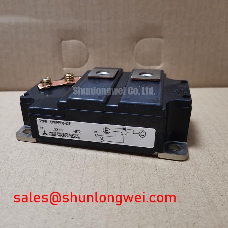
The Mitsubishi CM600HU-12F is an F-Series single IGBT module engineered for high-power switching applications requiring robust performance and thermal stability. Its core value lies in delivering a high 600A current capacity with efficient thermal dissipation, enabling the design of powerful and reliable inverters, motor drives, and power supplies. This module’s low thermal resistance is a key parameter for engineers developing compact systems, as it directly impacts heatsink requirements and overall thermal management strategy.
- Core Specifications: 600V | 600A | VCE(sat) 2.7V (max)
- Key Advantages: Facilitates robust high-power density designs, simplifies thermal management with low thermal impedance.
Download the Official CM600HU-12F Datasheet (PDF)

Technical Analysis for System Integration
The engineering value of the CM600HU-12F is defined by its capacity to manage substantial power throughput. A collector current (Ic) rating of 600A provides the necessary headroom for high-power applications like large motor controllers and welding systems. This high current capability, combined with a collector-emitter saturation voltage (VCE(sat)) of 2.2V (typical at 600A), creates a quantifiable balance between conduction losses and on-state performance. This allows designers to accurately model and predict system efficiency under heavy loads, a critical aspect of reliable power system design.
Effective thermal management is paramount in high-current modules. The CM600HU-12F features a low junction-to-case thermal resistance (Rth(j-c)) of 0.05°C/W for the IGBT. This parameter can be compared to the width of a pipe for heat removal; a lower value indicates a wider, less restrictive path for thermal energy to escape from the semiconductor chip to the heatsink. This efficiency minimizes the junction temperature rise for a given power dissipation, directly contributing to the module’s reliability and operational lifespan under demanding conditions. For further reading, explore the fundamentals of mastering IGBT thermal design.
Optimized Application Scenarios
The specifications of this module make it well-suited for several high-power industrial applications:
- Variable Frequency Drives (VFDs): The 600A current rating is ideal for controlling the speed and torque of large AC induction motors.
- Welding Power Supplies: Capable of handling the high-current, pulsed loads characteristic of industrial welding equipment. The module’s robust design ensures reliability in these harsh electrical environments.
- High-Capacity UPS Systems: The module’s ability to efficiently switch high currents makes it a reliable component for the inverter stage of large-scale uninterruptible power supplies.
- Industrial Servo Controls: Provides precise and powerful switching for large servo motors that require high dynamic performance.
Its high current capacity and efficient thermal path make it an excellent choice for systems requiring robust power switching without overly complex cooling solutions.
Key Specifications of the CM600HU-12F
| Absolute Maximum Ratings | ||
|---|---|---|
| Collector-Emitter Voltage (VCES) | 600V | |
| Gate-Emitter Voltage (VGES) | ±20V | |
| Collector Current (IC) | 600A | |
| Maximum Collector Dissipation (Pc) | 2500W | |
| Electrical & Thermal Characteristics | ||
| Collector-Emitter Saturation Voltage (VCE(sat)) (IC=600A) | 2.7V (Max) | |
| Gate-Emitter Threshold Voltage (VGE(th)) | 5.0 ~ 8.0V | |
| Turn-on Time (ton) | 0.6µs (Typ) | |
| Turn-off Time (toff) | 1.0µs (Typ) | |
| Thermal Resistance (Rth(j-c)) (IGBT) | 0.05°C/W (Max) | |
| Isolation Voltage (Viso) | 2500Vrms | |
Engineer’s FAQ for the CM600HU-12F
1. What is the main consideration for thermal design with the CM600HU-12F?
The primary task is to ensure the junction temperature (Tj) remains below its 150°C maximum rating. This involves calculating total power loss (conduction plus switching losses) for your specific operating conditions and using the module’s 0.05°C/W maximum thermal resistance to select a heatsink that can adequately dissipate the heat. An effective thermal management strategy is crucial.
2. What gate drive voltage is recommended for this module?
The datasheet specifies a gate-emitter threshold voltage (VGE(th)) between 5.0V and 8.0V. To ensure full saturation and minimize conduction losses, a positive gate voltage significantly higher than the maximum threshold is needed. A typical industrial practice is to use a +15V drive for turn-on and a negative voltage (e.g., -5V to -10V) for turn-off to provide strong noise immunity and prevent spurious turn-on. Always consult the principles of robust gate drive design.
3. Is the module’s baseplate electrically isolated?
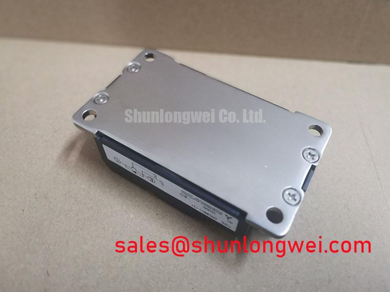
Yes. The CM600HU-12F features an isolated baseplate, rated for an isolation voltage (Viso) of 2500Vrms for one minute. This simplifies system assembly by allowing multiple modules to be mounted on a common, non-isolated heatsink without requiring separate insulating materials, reducing component count and potential assembly errors.
4. How do switching characteristics affect its use in an application like a VFD?
The typical turn-on (0.6µs) and turn-off (1.0µs) times dictate the module’s switching losses, which increase with frequency. For VFDs, these speeds are generally sufficient for PWM frequencies in the low-kilohertz range. Operating at higher frequencies would increase switching losses and thermal load, potentially requiring a more substantial cooling solution.
Enabling High-Power System Design
The Mitsubishi CM600HU-12F provides a direct path for engineers to implement high-current power stages. Its combination of a 600A rating, well-defined switching characteristics, and efficient thermal pathway simplifies the challenges of high-power design. This module serves as a robust foundation for building reliable and powerful industrial conversion systems.