Fuji 6MBI450U-120 IGBT Module: A Technical Analysis
Fuji Electric 6MBI450U-120 IGBT Module: Technical Review
Introduction and Core Highlights
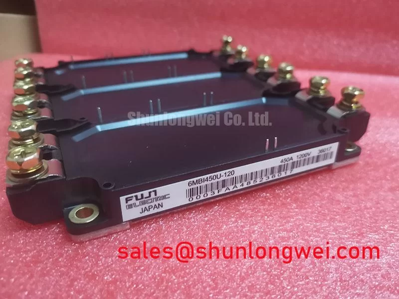
The Fuji Electric 6MBI450U-120 is a U-Series IGBT module engineered for high-speed power conversion systems. This module integrates six IGBTs in a single package, providing a robust solution for three-phase inverter applications. Its design focuses on achieving a balance between low conduction losses and fast switching capabilities, enabled by Fuji Electric’s trench gate and field-stop (FS) chip technology. This approach allows for efficient operation in demanding industrial environments.
- Core Specifications: 1200V | 450A | VCE(sat) (typ) 2.2V
- Key Advantages: High-speed switching performance, low internal inductance module structure.
- Engineering Value: Facilitates higher inverter operating frequencies, contributes to reduced thermal management requirements.
For detailed electrical and thermal characteristics, refer to the official manufacturer’s documentation. Download the 6MBI450U-120 Datasheet (PDF)

Technical Analysis: Performance Under Load
The engineering value of the 6MBI450U-120 is rooted in its electrical characteristics, which are optimized for efficiency. The collector-emitter saturation voltage (VCE(sat)) is specified with a typical value of 2.2V at its nominal current (IC = 450A) and a junction temperature of 125°C. This parameter is critical as it directly influences the conduction losses during operation. Think of VCE(sat) as the resistance of a valve when it’s fully open; a lower value signifies that less energy is converted into waste heat, allowing for more efficient power delivery and potentially smaller heatsinks.
Complementing the low conduction loss is the module’s switching performance. The datasheet specifies a typical turn-on time (ton) of 0.60µs and a turn-off time (toff) of 0.37µs under nominal conditions. These rapid switching times are essential for applications like high-frequency inverters, as they minimize the energy lost during the transition between on and off states. The low inductance design of the module package further supports this high-speed capability by reducing voltage overshoots and oscillations, which is a key aspect of maintaining system reliability.


Optimized Application Scenarios
The specific parameter set of the 6MBI450U-120 makes it a strong candidate for several high-power industrial applications:
- Inverters for Motor Drives: The module’s 450A continuous current rating and fast switching characteristics are well-suited for controlling large AC induction motors with precision and efficiency.
- Uninterruptible Power Supplies (UPS): High reliability and low total power loss are critical in UPS systems. The low VCE(sat) of this module contributes directly to higher operational efficiency.
- AC and DC Servo Drive Amplifiers: Servo drives demand rapid response and high current capability. The module’s performance enables the dynamic control required in robotics and CNC machinery.
- Welding Machines: The robust current handling (900A peak) and thermal stability are beneficial for the pulsed power demands found in industrial welding power supplies.
This module is an optimal match for three-phase power stages requiring efficient switching of currents up to 450A with a 1200V blocking voltage capability.
Key Specifications of the 6MBI450U-120
| Absolute Maximum Ratings (Tc=25°C) | ||
|---|---|---|
| Parameter | Symbol | Value |
| Collector-Emitter Voltage | VCES | 1200 V |
| Gate-Emitter Voltage | VGES | ±20 V |
| Continuous Collector Current (Tc=80°C) | IC | 450 A |
| Peak Collector Current (1ms) | ICp | 900 A |
| Max Power Dissipation (1 device) | PC | 2080 W |
| Operating Junction Temperature | Tj | +150 °C |
| Thermal Characteristics | ||
| Thermal Resistance (Junction-to-Case, IGBT) | Rth(j-c) | 0.06 °C/W |
| Contact Thermal Resistance (with thermal compound) | Rth(c-f) | 0.0167 °C/W |
Engineer’s FAQ
- How does the thermal resistance impact heatsink selection for the 6MBI450U-120?
- The thermal resistance from junction to case (Rth(j-c)) is very low at 0.06 °C/W per IGBT. This value is a critical input for calculating the required heatsink performance. A lower Rth(j-c) indicates more efficient heat transfer from the semiconductor chip to the module’s baseplate, easing the requirements for the external cooling system. Proper thermal design, including the use of thermal compound as specified by the Rth(c-f) value, is essential for maintaining the junction temperature below the 150°C maximum. For further reading, consult resources on mastering IGBT thermal design.
- What are the recommended mounting torque settings?
- The datasheet specifies a recommended mounting screw torque of 3.5 to 4.5 N·m for the M6 mounting holes. The terminal screws (M5) should be torqued to 2.5 to 3.5 N·m. Adhering to these values is crucial to ensure a low-resistance thermal and electrical connection without inducing mechanical stress on the module.
- Is an NTC thermistor included in this module?
- Yes, the equivalent circuit diagram in the datasheet confirms the presence of an integrated NTC thermistor for temperature monitoring. This feature allows the control system to monitor the module’s approximate temperature, enabling over-temperature protection and enhancing overall system safety, a key consideration discussed in articles about the role of the NTC in IGBT reliability.
Concluding Statement
The Fuji Electric 6MBI450U-120 provides system designers with a high-current, 6-in-1 power semiconductor solution. Its U-Series technology delivers a well-balanced profile of low conduction losses and fast switching speeds. This enables the development of more efficient and compact high-power inverters for a range of industrial applications.