Toshiba MIG30J901H: An Integrated IGBT Module for Compact Motor Drives
Toshiba MIG30J901H 600V 30A 6-in-1 IGBT Module
Introduction and Core Highlights
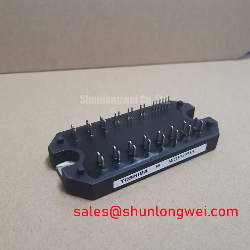
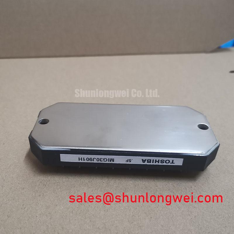
The Toshiba MIG30J901H is a Silicon N Channel IGBT Module that integrates a full three-phase inverter bridge into a single, compact package. This module’s primary value is its functional integration, which simplifies power stage design and assembly for motor control applications. By consolidating six IGBTs and six free-wheeling diodes, it provides a streamlined solution that reduces both component count and required PCB space, directly addressing the need for more compact and reliable drive systems.
- Core Specifications: 600V | 30A | VCE(sat) 2.7V (Typ)
- Key Advantages: Simplifies thermal management to a single heatsink interface, reduces stray inductance for improved EMI performance.
For engineers designing small to medium variable frequency drives, this module offers a balance of performance and integration.
Download Official Datasheet (PDF)


Technical Analysis of the Integrated Power Stage
The core engineering benefit of the MIG30J901H is the consolidation of the inverter power stage. This architecture inherently reduces parasitic inductance between components compared to a discrete solution. Lower inductance leads to cleaner switching waveforms, reduced voltage overshoot, and consequently, lower electromagnetic interference (EMI). This allows for a more robust design with potentially smaller and less costly snubber circuits. For more information on this topic, see our guide to the impact of parasitic inductance on IGBT performance.
A critical parameter for evaluating efficiency is the collector-emitter saturation voltage, VCE(sat). The MIG30J901H specifies a typical VCE(sat) of 2.7V at its rated 30A current and a junction temperature of 125°C. You can think of VCE(sat) as a measure of electrical friction; a lower value indicates that less power is converted into waste heat when the IGBT is fully on. This module’s VCE(sat) represents a balanced trade-off between conduction losses and switching speed, making it suitable for a wide range of motor control frequencies.
Optimized Application Scenarios
The specifications of the MIG30J901H make it a strong candidate for several power conversion applications:
- Variable Frequency Drives (VFDs): Its 6-in-1 integration is ideal for compact VFDs used to control AC induction motors in pumps, fans, and conveyors. The single-package design simplifies assembly and improves reliability.
- Servo Drives: In automation and robotics, the module’s defined switching characteristics enable the precise current control necessary for accurate motor positioning.
- HVAC Systems: For air conditioning and heating systems, this module can efficiently drive variable-speed compressors and fans, contributing to overall energy savings.
- General-Purpose Inverters: The module’s robust voltage and current ratings are well-suited for uninterruptible power supplies (UPS) and other low-to-mid-power three-phase inverter topologies.
This module is best matched for motor drive applications under 5 kW requiring a simplified, reliable, and space-saving power stage.
Key Specifications of the MIG30J901H
| Absolute Maximum Ratings (Ta = 25°C) | |
|---|---|
| Collector-Emitter Voltage (VCES) | 600 V |
| Collector Current (IC) | 30 A |
| Forward Current (IF) | 30 A |
| Collector Power Dissipation (PC) | 130 W |
| Junction Temperature (Tj) | 150 °C |
| Electrical Characteristics (Ta = 25°C unless otherwise noted) | |
| Collector-Emitter Saturation Voltage (VCE(sat)) @ 30A, 125°C | 2.7 V (Typ) |
| Diode Forward Voltage (VF) @ 30A, 125°C | 2.0 V (Typ) |
| Gate-Emitter Leakage Current (IGES) | ±500 nA |
| Short Circuit Withstand Time (tsc) | 10 µs |
Engineer’s FAQ
- What are the primary advantages of using a 6-in-1 module like the MIG30J901H versus discrete IGBTs?
- The main benefits are design simplification, reduced assembly time, and improved thermal performance. A single module requires one heatsink mounting operation and has matched internal components, which can lead to more predictable performance and better EMI characteristics than a layout with six separate transistors and diodes.
- What is the recommended mounting procedure for this module to ensure proper cooling?
- The datasheet specifies a recommended mounting screw torque (typically M4 screws). It is critical to apply a thin, uniform layer of thermal grease to the isolated baseplate before mounting it to a flat, clean heatsink. Applying the correct torque ensures optimal thermal contact without inducing mechanical stress on the module.
- How does VCE(sat) impact the thermal design of my system?
- VCE(sat) directly determines the conduction power loss (P = VCE(sat) * IC). A higher VCE(sat) means more heat is generated for the same amount of current. This requires a larger heatsink or more airflow to keep the IGBT’s junction temperature within its safe operating limits. For a deeper understanding, explore our articles on mastering IGBT thermal design.
Enabling Compact and Reliable Motor Control
The Toshiba MIG30J901H provides a robust, all-in-one solution for power engineers tasked with developing efficient and compact three-phase inverter systems. Its integrated architecture and balanced electrical characteristics reduce design complexity, providing a solid foundation for reliable motor control applications. This approach allows design teams to focus on system-level innovation rather than the intricacies of discrete power stage layout and component matching.