Fuji 7MBR75U4B120-50: A Technical Analysis of the 1200V 75A 7-in-1 IGBT Module
Fuji 7MBR75U4B120-50 IGBT PIM | 1200V 75A 7-in-1 Module
Introduction and Core Highlights
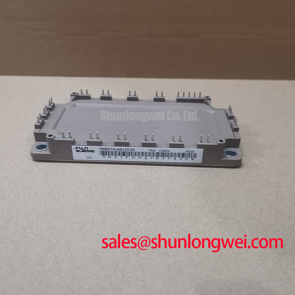
The Fuji Electric 7MBR75U4B120-50 is a Power Integrated Module (PIM) that provides a comprehensive power stage solution for compact inverter designs. This module’s primary value is its high level of integration, combining a three-phase diode rectifier, a three-phase IGBT inverter, and an IGBT brake chopper into a single housing. This consolidation simplifies the design of motor drives and power converters by significantly reducing component count, minimizing PCB size, and streamlining thermal management.
- Core Specifications: 1200V | 75A (Inverter) | 7-in-1 CIB Configuration
- Key Advantages: Reduces system complexity and assembly costs, enhances thermal efficiency with a single isolated baseplate.
For engineers seeking to accelerate development and increase power density, this integrated architecture offers a clear path to more efficient and reliable power systems.
Download Official Datasheet (PDF)

Technical Analysis of the Integrated Design
The engineering value of the 7MBR75U4B120-50 lies in its 7-in-1 Converter-Inverter-Brake (CIB) topology. By housing the AC-DC rectification stage, the DC-AC inverter stage, and the regenerative braking circuit in one module, it solves several critical design challenges. This integration reduces the parasitic inductance that typically occurs in layouts with discrete components, leading to cleaner switching waveforms and potentially lower EMI. For further reading on this topic, consider exploring the differences between PIM vs. discrete IGBT solutions.
A crucial parameter for any power module is its thermal resistance, Rth(j-c). You can think of thermal resistance as the width of a pipeline for heat; a lower value signifies a wider pipe, allowing heat to flow away from the active silicon more easily. The specified thermal resistance for this module ensures efficient heat transfer to an external heatsink, which is fundamental for achieving the stated current ratings and ensuring long-term operational reliability. This efficiency is further supported by the module’s use of 4th generation U-series IGBTs, which balance low on-state voltage (VCE(sat)) with controlled switching losses to minimize heat generation at the source.
Optimized Application Scenarios
The specific features of the 7MBR75U4B120-50 make it a strong candidate for several applications:
- AC Motor Drives: Its all-in-one CIB configuration provides the complete power stage for compact variable frequency drives (VFDs) used in pumps, fans, and conveyors.
- Servo Drives: The integrated braking circuit is essential for applications requiring rapid deceleration and precise position control.
- Uninterruptible Power Supplies (UPS): The converter and inverter sections are directly applicable to the core power conversion stages of online UPS systems.
- Industrial Power Converters: Suitable for various general-purpose inverters where space and assembly simplicity are key considerations.
This module is an optimal match for motor control systems requiring a complete and reliable power stage in a compact form factor.

Key Specification Parameters
| Absolute Maximum Ratings (Tc = 25°C) | ||
|---|---|---|
| Parameter | Symbol | Value |
| Inverter & Brake Section | ||
| Collector-Emitter Voltage | VCES | 1200 V |
| Collector Current (DC) | IC | 75 A |
| Converter Section | ||
| Repetitive Peak Reverse Voltage | VRRM | 1200 V |
| Average Forward Current | IF(AV) | 75 A |
| Module | ||
| Operating Junction Temperature | Tj | +150 °C |
Engineer’s FAQ
- What are the primary benefits of using a 7-in-1 PIM like the 7MBR75U4B120-50 versus discrete components?
- The main advantages are design simplification, reduced assembly time, and a smaller physical footprint. Integrating the rectifier, inverter, and brake circuit into one module minimizes external connections, lowers parasitic inductance, and provides a centralized thermal path for easier heatsink design.
- What is the recommended mounting torque for this module, and why is it important?
- The official datasheet specifies a recommended mounting torque for the terminal and mounting screws. Adhering to this specification is critical for two reasons: it ensures a secure electrical connection to prevent overheating and guarantees proper physical contact with the heatsink for effective thermal dissipation.
- Does this module include an NTC thermistor?
- Yes, the datasheet confirms the inclusion of an NTC thermistor. This component allows for real-time monitoring of the module’s internal temperature, enabling over-temperature protection mechanisms in the control system, which is crucial for IGBT module safety and reliability.
- What are the typical gate drive voltage requirements for the IGBTs?
- The datasheet indicates a recommended gate-emitter voltage (VGE) of +15V for turn-on and specifies the gate-emitter threshold voltage. A stable and well-regulated gate drive circuit is essential for achieving the specified switching performance and preventing issues like parasitic turn-on. For more information, see our guide on robust gate drive design.
Enabling Compact and Efficient Power Conversion
The 7MBR75U4B120-50 module delivers a functionally complete power stage in an optimized package. By integrating key circuit blocks, this PIM allows engineers to focus on system-level control and functionality, ultimately enabling the development of more compact, cost-effective, and reliable motor drives and power converters.