A Technical Analysis of the Mitsubishi PM200CVA060 Intelligent Power Module
PM200CVA060 Mitsubishi Intelligent Power Module Analysis
Integrated Protection and Drive for 600V Inverters
The Mitsubishi PM200CVA060 is an Intelligent Power Module (IPM) that integrates a complete three-phase inverter power circuit, dedicated gate drive, and protection logic into a single insulated package. This module’s primary value is its high level of integration, which simplifies system design and enhances reliability by providing built-in protection against short circuits and over-temperature events. It eliminates the need for separate gate drivers and complex monitoring circuits.
- Core Specifications: 600V | 200A | VCE(sat) 2.2V (typ)
- Key Advantages: Reduces component count and simplifies PCB layout. Provides robust, self-contained system protection.
This integrated approach helps answer a critical question for engineers: how to ensure robust protection without complex external circuitry. The PM200CVA060 directly addresses this by incorporating logic for short circuit, over-temperature, and control supply under-voltage protection.
Download The Official PM200CVA060 Datasheet (PDF)
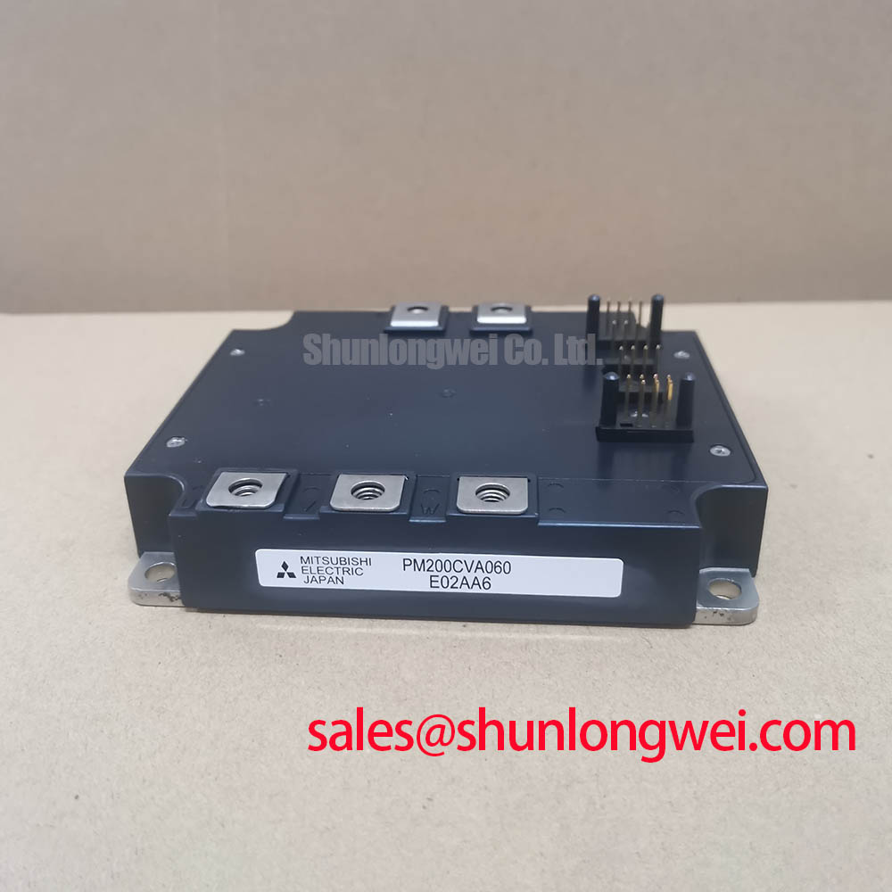
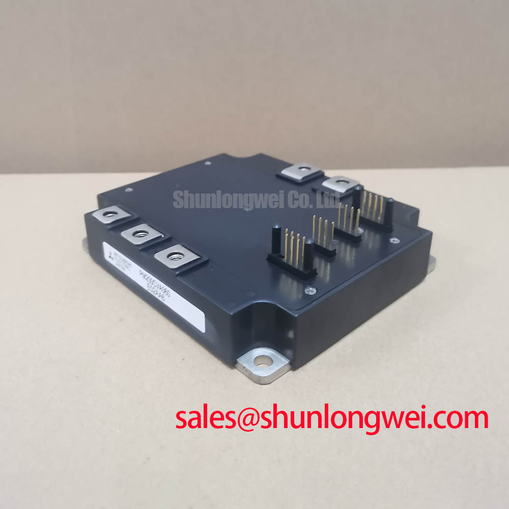


Technical Analysis: Integration and Thermal Performance
The core engineering advantage of the PM200CVA060 is its integration. By housing the six IGBTs, free-wheeling diodes, and control circuits in one module, it minimizes the parasitic inductance that can cause voltage overshoots in discrete designs. This allows for cleaner switching at frequencies up to 20 kHz. The module’s control logic is optimized to provide the correct gate drive voltage and protection, which removes significant design overhead compared to building a gate drive circuit from scratch.
A critical parameter for power module reliability is thermal resistance. The PM200CVA060 specifies a junction-to-case thermal resistance (Rth(j-c)Q) of 0.231 °C/W for the IGBT portion. Think of thermal resistance as the width of a pipe for heat; a lower value signifies a wider pipe, allowing heat to escape more efficiently from the semiconductor junction to the case and heatsink. This efficient heat extraction is vital for maintaining the junction temperature within the safe operating area, especially under high current loads.
Optimized Application Scenarios
The characteristics of the PM200CVA060 make it suitable for a range of power conversion applications.
- General Purpose Inverters: Its 200A current rating and integrated protection are well-suited for industrial motor drives where reliability is paramount.
- AC Servo Drives: The module’s ability to operate efficiently up to 20 kHz allows for precise and quiet motor control.
- Uninterruptible Power Supplies (UPS): The robust short-circuit protection and defined thermal performance ensure dependable operation during critical power backup events.
- Welding Power Supplies: The high peak current capability (Icp = 400A) can handle the pulsed load demands typical of welding applications.
With its comprehensive feature set, this module is an optimal match for three-phase inverter systems requiring simplified design, high reliability, and robust fault management.
Key Specifications of the PM200CVA060
| Absolute Maximum Ratings (Tj = 25°C) | |
|---|---|
| Collector-Emitter Voltage (VCES) | 600 V |
| Collector Current (IC) | 200 A |
| Peak Collector Current (ICP) | 400 A |
| Collector Dissipation (PC) | 595 W |
| Junction Temperature (Tj) | -20 to 150 °C |
| Isolation Voltage (Viso) | 2500 Vrms |
| Electrical Characteristics (Tj = 25°C) | |
| Collector-Emitter Saturation Voltage (VCE(sat)) at IC=200A | 2.20 V (typ), 3.30 V (max) |
| FWDi Forward Voltage (VEC) at -IC=200A | 2.20 V (typ), 3.30 V (max) |
| Control Supply Under Voltage Trip Level (UV) | 12.0 V (typ) |
| Thermal and Mechanical Characteristics | |
| Thermal Resistance, Junction-to-Case (Rth(j-c)Q, IGBT) | 0.231 °C/W |
| Mounting Torque (M5 Screws) | 2.5 – 3.5 N·m |
Engineer’s FAQ
What are the specific protection functions integrated into the PM200CVA060?
The module includes protection for short circuits (SC), over-temperature (OT) via an internal temperature sensor, and control supply under-voltage (UV) for all internal drive circuits. These protections trigger a fault signal output (FO).
What is the recommended mounting procedure to ensure proper thermal contact?
The datasheet specifies a mounting torque of 2.5 to 3.5 N·m for the M5 mounting screws. It is critical to apply a uniform layer of thermal grease and follow the specified torque to minimize contact thermal resistance (Rth(c-f)) and ensure effective heat transfer to the heatsink. For a deeper understanding of thermal management, refer to this guide on mastering IGBT thermal design.
How is the short circuit protection implemented?
The module utilizes advanced current-sense IGBT chips. These chips allow the internal control logic to continuously monitor the collector current. If a short circuit event causes the current to exceed a predefined threshold, the control circuit performs a soft shutdown of the IGBT to protect it from damage and sends a fault signal. The supply voltage protected by this feature (VCC(prot.)) is 400V.
What are the logic levels for the control inputs?
The inputs are compatible with common logic levels. The “ON” threshold voltage is typically 1.5V (max 1.8V), and the “OFF” threshold is typically 2.0V (min 1.7V), ensuring good noise immunity. This simplifies the interface with microcontrollers and FPGAs. To learn more about IPMs check out our guide to the IPM advantage.
Design and Reliability
The PM200CVA060 provides engineers with a pre-validated subsystem for three-phase power conversion. By integrating the power stage with optimized drive and protection circuits, this module allows design teams to focus on system-level objectives, reduce time-to-market, and increase the overall reliability and robustness of the end application. Its documented performance and protective features offer a dependable foundation for industrial power electronics.