PM150CS1D060 IPM: A Technical Analysis for Simplified Motor Control Design
PM150CS1D060: 600V 150A CIB Intelligent Power Module
Introduction and Core Highlights
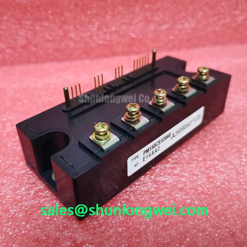
The Mitsubishi PM150CS1D060 is a highly integrated Intelligent Power Module (IPM) that combines a three-phase converter, inverter, and brake (CIB) circuit into a single, compact package. This integration provides a streamlined solution for motor control systems by incorporating optimized gate drive and protection circuits, which significantly simplifies the overall design process. The module is engineered to reduce component count and enhance system reliability for various industrial applications.
- Core Specifications: 600V | 150A | CIB (Converter-Inverter-Brake) Configuration
- Key Advantages: Reduces system size and assembly time, integrates critical protection for enhanced reliability.
By housing the complete power stage in one component, this module helps engineers minimize the parasitic inductance that often complicates designs using discrete components.
Download Official Datasheet (PDF)

Technical Analysis of the Integrated Design
The primary engineering value of the PM150CS1D060 lies in its high level of integration. Consolidating the rectifier bridge, three-phase inverter, and brake chopper into one module offers more than just space savings. This design minimizes the internal wiring and connection points, leading to lower stray inductance—a critical factor in reducing voltage overshoots during high-speed switching. This allows for cleaner switching waveforms and potentially lower EMI, simplifying system-level filtering and compliance efforts.
Built-in Protection for System Robustness
A key feature documented in the datasheet is the suite of integrated protection circuits. The module includes detection for short-circuits (SC), over-temperature (OT), and control supply under-voltage (UV). Think of this integrated protection as a vehicle’s comprehensive safety system. Instead of adding separate, external circuits for each potential fault, the PM150CS1D060 has them built-in. This enables a faster, more reliable response to fault conditions, protecting not only the IPM itself but also the motor and other connected systems from catastrophic failure. This integration reduces the external component count and accelerates the development of reliable power semiconductor systems.
Optimized Application Scenarios
The specifications of the PM150CS1D060 make it well-suited for a range of motor control applications:
- General Purpose Inverters: The all-in-one CIB configuration provides a complete power stage, simplifying the design and manufacturing of compact variable frequency drives (VFDs).
- AC Servo Drives: The integrated protection and low-inductance package support the precise and reliable control required in high-performance servo systems.
- Industrial Motor Control: For applications like fans, pumps, and conveyors, this module offers a robust and space-saving solution that enhances long-term reliability.
This module is an excellent fit for motor control systems requiring a compact design footprint and high operational reliability.
Key Specifications of the PM150CS1D060
| Parameter | Symbol | Conditions | Value |
|---|---|---|---|
| Absolute Maximum Ratings (Tj = 25°C unless otherwise noted) | |||
| Collector-Emitter Voltage (Inverter) | VCES | – | 600V |
| Collector Current (Inverter) | ±IC | Tc = 25°C | 150A |
| Collector Power Dissipation (Inverter) | PC | Tc = 25°C | 595W |
| Junction Temperature | Tj | – | -20 to +150°C |
| Electrical Characteristics (Tj = 25°C) | |||
| Collector-Emitter Saturation Voltage | VCE(sat) | IC = 150A, VD = 15V | 2.2V (Typ) |
| Isolation Voltage | Viso | AC 1 min, 60Hz Sinusoidal | 2500Vrms |
| Thermal Characteristics | |||
| Thermal Resistance (Inverter IGBT) | Rth(j-c) | Per 1 element | 0.21°C/W (Max) |
Engineer’s FAQ
What are the main advantages of using the PM150CS1D060 CIB module over a discrete solution?
The primary benefits are reduced design complexity, smaller PCB footprint, and improved reliability. The integrated gate driver, protection circuits, and optimized internal layout minimize parasitic inductance and simplify thermal management compared to designing with individual components. This leads to a shorter time-to-market.
What are the mounting recommendations for this module to ensure proper thermal performance?
The datasheet specifies a mounting torque for the terminals and main mounting holes. It is critical to apply a uniform layer of thermal grease between the module’s baseplate and the heatsink to minimize contact thermal resistance. Ensure the heatsink surface is flat and clean before installation.
How does the over-temperature (OT) protection work?
The module contains an internal temperature sensor. If the internal temperature exceeds a predefined limit (typically around 125°C to 150°C), the control circuit triggers a fault signal (Fo) and shuts down the IGBTs to prevent thermal damage. Read more about the importance of integrated thermal sensing.
What is the purpose of the integrated brake chopper circuit?
The brake chopper is used to dissipate regenerative energy from the motor, which occurs during deceleration. It connects to an external braking resistor and prevents the DC bus voltage from rising to dangerous levels, protecting the module and other DC link components.
Enabling Compact and Reliable Power Designs
The PM150CS1D060 IPM delivers a robust, factory-tested power stage that empowers engineers to focus on system-level innovation rather than discrete-level complexities. Its combination of power density, integrated protections, and CIB topology provides a solid foundation for developing efficient and durable motor control solutions. To understand more about the benefits of integrated designs, explore this analysis on the IPM advantage.