Infineon FF1400R17IP4: A Technical Review for High-Power Applications
Infineon FF1400R17IP4 | 1700V 1400A IGBT Module
High Power Density for Megawatt-Scale Inverters
The Infineon FF1400R17IP4 is a high-power IGBT module engineered for demanding power conversion systems. It leverages Infineon’s proven Trench/Fieldstop IGBT4 technology to deliver a massive current handling capability within a standard industrial footprint. This combination enables the design of robust and power-dense inverters for multi-megawatt applications.
- Core Specifications: 1700V | 1400A | Tvj op 150°C
- Key Advantages: Enables maximum power throughput, simplifies thermal management.
For systems requiring high reliability under demanding thermal loads, this module’s low thermal resistance is a critical parameter for ensuring longevity. For complete specifications, please download the official datasheet (PDF).
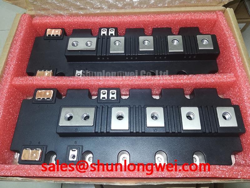

Technical Analysis for System Integration
The standout feature of the FF1400R17IP4 is its nominal collector current (IC nom) of 1400A. This high rating allows a single module to manage significant power, which can simplify system architecture by reducing the need for complex paralleling schemes. This is a direct benefit for designers of large-scale multi-level inverters, where minimizing component count is key to improving reliability and serviceability.
Effective thermal management is fundamental in high-power applications. The module specifies a low thermal resistance from junction to case (RthJC) of 0.0085 K/W per IGBT. To put this into perspective, think of thermal resistance as the width of a pipe draining heat from the component. A lower value, like the one found in this module, represents a wider pipe, facilitating rapid and efficient heat transfer to the heatsink. This efficiency is critical for maintaining the junction temperature within its maximum operating limit of 150°C, even under heavy load cycles.
The module is built upon Infineon’s established Trench/Fieldstop IGBT4 technology. This technology offers a well-balanced performance between conduction losses, characterized by the collector-emitter saturation voltage (VCEsat), and switching losses (Eon/Eoff). With a typical VCEsat of 2.50V at 1400A and 125°C, it provides predictable performance for achieving high system efficiency in applications operating at moderate switching frequencies.
Optimized Application Scenarios
The specifications of the FF1400R17IP4 make it a strong candidate for several high-power industrial applications:
- Wind Turbine Inverters: The 1700V blocking voltage and 1400A current rating are ideal for converting the high-power DC output from multi-megawatt turbines.
- Industrial Motor Drives: Its ability to handle high currents and its robust thermal performance make it suitable for large industrial motors in mining, pumping, and manufacturing.
- Uninterruptible Power Supplies (UPS): For data centers and critical facilities, the module’s high reliability and power rating ensure dependable backup power.
- Traction Systems: The robust IHM-B housing and high surge current capability are beneficial for rail and heavy-duty vehicle propulsion systems.
This module is an optimal match for megawatt-scale power conversion systems requiring high current throughput and proven thermal stability.
Key Specification Parameters
| Parameter | Symbol | Value | Condition |
|---|---|---|---|
| Absolute Maximum Ratings | |||
| Collector-Emitter Voltage | VCES | 1700 V | Tvj = 25°C |
| Continuous DC Collector Current | IC nom | 1400 A | – |
| Repetitive Peak Collector Current | ICRM | 2800 A | tP = 1 ms |
| Gate-Emitter Peak Voltage | VGES | ±20 V | – |
| Electrical & Thermal Characteristics | |||
| Collector-Emitter Saturation Voltage | VCEsat (typ.) | 2.50 V | IC = 1400 A, VGE = 15 V, Tvj = 125°C |
| Gate Threshold Voltage | VGE(th) | 5.2 V – 6.4 V | IC = 50.0 mA, Tvj = 25°C |
| Thermal Resistance, Junction-to-Case | RthJC | 0.0085 K/W | Per IGBT |
| Operating Junction Temperature | Tvj op | -40 to 150 °C | Under switching conditions |
Engineer’s FAQ
What is the primary consideration for the thermal design when using the FF1400R17IP4?
The most critical factor is ensuring the cooling system can leverage the module’s low junction-to-case thermal resistance (0.0085 K/W per IGBT). A properly designed heatsink and thermal interface are essential to keep the operating junction temperature below the 150°C maximum during all load conditions. This ensures both performance and long-term reliability.
How does the module’s package design facilitate installation?
The FF1400R17IP4 is housed in an industry-standard IHM-B package (190mm x 140mm). This standardized design features robust screw terminals for secure power connections and an isolated baseplate, simplifying mounting procedures and ensuring high electrical isolation (4 kV AC for 1 min) from the heatsink.
What level of short-circuit protection is provided?
According to the datasheet, the module has a short-circuit withstand time (tSC) of 10 µs at a DC link voltage of 1000V (Tvj ≤ 125°C). This allows sufficient time for the gate drive protection circuitry to detect a fault and safely turn off the IGBT, preventing catastrophic failure.
Enabling High-Power System Design
The Infineon FF1400R17IP4 provides a robust, high-current foundation for demanding power inverter designs. Its combination of a 1400A rating, efficient thermal characteristics, and proven IGBT4 technology empowers engineers to develop power-dense and reliable megawatt-class systems. This makes it a strategic component for advancing technologies in renewable energy and high-power industrial automation.