A Technical Review of the Mitsubishi PM15CMA060-1 Intelligent Power Module
PM15CMA060-1 | Mitsubishi 600V 15A Intelligent Power Module
Introduction and Core Highlights
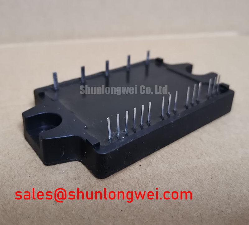
The Mitsubishi PM15CMA060-1 is a highly integrated 3-phase Intelligent Power Module (IPM) that combines a full IGBT bridge, gate drive circuitry, and comprehensive protection features into a single, compact package. Its primary value is in streamlining the design of low-power motor control systems by delivering a pre-validated and protected power stage. This integration significantly reduces component count and simplifies PCB layout, accelerating development cycles. For engineers designing compact motor drives, the PM15CMA060-1 offers a robust foundation with built-in safeguards against common failure modes.
* **Core Specifications**: 600V VCE | 15A Ic | 2500Vrms Isolation Voltage
* **Key Advantages**: Simplifies gate drive and control logic, enhances system reliability with integrated protection.
* **Reduces Development Time**: Minimizes the need for external protection components and complex driver circuits.
Download the PM15CMA060-1 Datasheet (PDF)
Technical Analysis: Integration for System Reliability
A key engineering advantage of the PM15CMA060-1 is its comprehensive suite of built-in protection circuits. The module provides real-time protection against over-current (OC), short-circuits (SC), earth faults, under-voltage (UV), and over-temperature (OT) conditions. This integrated safety net acts like a vigilant supervisor for the power stage, capable of shutting down the IGBTs to prevent catastrophic damage before it occurs. This is a critical feature that simplifies meeting system safety standards and improves the overall robustness of the end application.
The thermal resistance of a power module is a crucial parameter for effective heat management. You can think of thermal resistance like the width of a pipe; a lower value means heat can flow away from the IGBT junctions more easily, keeping the device within its safe operating temperature. The datasheet specifies the thermal resistance from junction to case (Rth(j-c)), which is essential for accurate heatsink selection and thermal modeling. Proper thermal management is fundamental to achieving long-term operational reliability.

Optimized Application Scenarios
The PM15CMA060-1 is engineered for specific low-power inverter applications where reliability and a compact footprint are paramount.
* **AC Motor Speed Controllers**: The module’s 3-phase bridge topology is a direct fit for small variable frequency drives (VFDs).
* **Brushless Servo Drives**: High integration and built-in protection are essential for the precision and reliability required in servo systems.
* **Uninterruptible Power Supplies (UPS)**: The robust inverter stage and protection features make it suitable for smaller UPS designs.
* **Appliance Motor Control**: Ideal for driving motors in appliances like washing machines or air conditioning units.
Its all-in-one design makes the PM15CMA060-1 an excellent match for applications up to 2kW requiring simplified assembly and enhanced system protection.
Key Specifications of the PM15CMA060-1
| Parameter | Value |
|---|---|
| Absolute Maximum Ratings (Power Circuit) | |
| Collector-to-Emitter Voltage (VCE) | 600V |
| Continuous Collector Current (Ic @ Tc=85°C, 1 IGBT) | 7.0A |
| Supply Voltage (P-N) | 450V |
| Power Dissipation (Po @ Tc=85°C, 1 IGBT) | 22W |
| Operating Junction Temperature (Tj) | -20 to 150°C |
| Electrical Characteristics (Tj = 25°C) | |
| Collector-Emitter Saturation Voltage (VCE(sat)) @ 15A | 2.7V (Typ) |
| Turn-On Switching Time (ton) | 1.5µs (Typ) |
| Turn-Off Switching Time (toff) | 2.5µs (Typ) |
| System Ratings | |
| RMS Isolation Voltage (Visol, 1 Minute) | 2500V |
| Case Operating Temperature (Tc) | -20 to 100°C |
Note: These parameters are summaries. For complete specifications, refer to the official datasheet.
Engineer’s FAQ
What specific fault conditions does the PM15CMA060-1 protect against?
The module includes integrated protection against over-current, short-circuits, earth faults, control supply under-voltage, and over-temperature. It provides a fault feedback signal (VFO) to the microcontroller for system-level diagnostics.
What is the recommended mounting torque for this module?
The datasheet specifies a mounting torque of 2.0 Nm. Applying the correct torque is critical for ensuring low thermal resistance between the module’s baseplate and the heatsink. Insufficient torque can create air gaps that impede heat transfer, while excessive torque can damage the module’s substrate.
How does the fault output (VFO) pin function?
The VFO pin is an open-collector output. In normal operation, it remains in a high-impedance state. When a fault (like over-current or under-voltage) is detected, the VFO output is pulled low, signaling an error condition to the system’s controller. This allows for immediate and safe shutdown procedures.
What is the role of an Intelligent Power Module (IPM) in a power system?
An IPM, like the PM15CMA060-1, combines the power switching devices (IGBTs) with the gate drive circuits and protection logic in a single module. This simplifies the design process, reduces PCB space, improves noise immunity, and increases overall system reliability compared to using discrete components.
Enabling Robust Power Control
The PM15CMA060-1 delivers a verified and protected power stage that enables engineers to focus on system-level innovation rather than discrete component-level design. By integrating the core elements of a low-power inverter, this power semiconductor module provides a dependable and efficient path to developing compact motor drives and other inverter systems.