A Technical Guide to the Mitsubishi CM150TX-24S IGBT Module
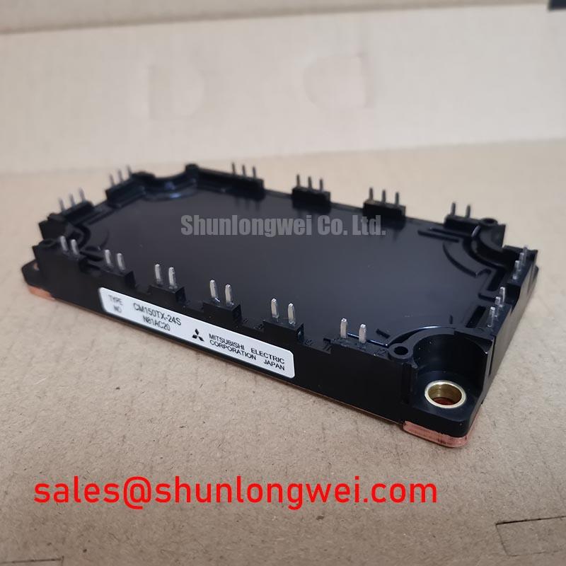
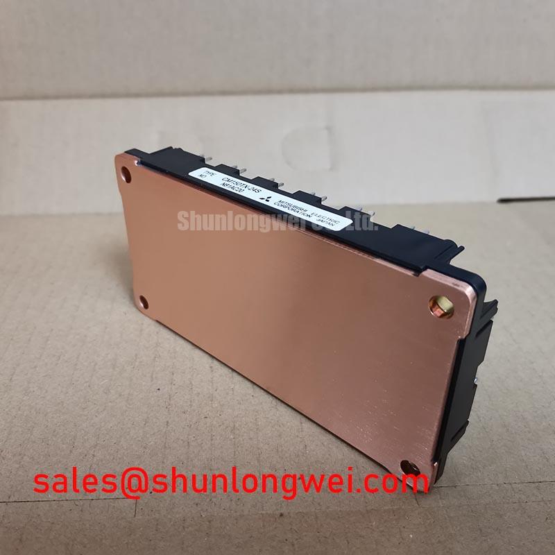
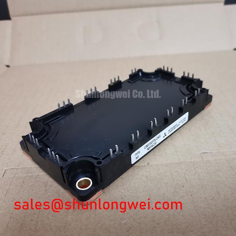
Mitsubishi CM150TX-24S | 1200V 150A S-Series IGBT Module
Engineered for High-Efficiency Power Conversion
The Mitsubishi CM150TX-24S is an S-Series IGBT (Insulated Gate Bipolar Transistor) module that delivers a distinct balance of low power loss and robust operational reliability. Its core value is rooted in a low collector-emitter saturation voltage (VCE(sat)) and substantial short-circuit withstand capability, enabling the design of highly efficient and durable power systems for demanding industrial applications.
- Core Specifications: 1200V | 150A | VCE(sat) of 1.7V (typ)
- Key Advantages: Minimizes conduction losses for greater system efficiency and offers a 10µs short-circuit withstand time for enhanced system protection.
- Design Focus: The module’s thermal characteristics are well-defined, providing a clear path for engineers to design effective cooling solutions, ensuring long-term operational stability.
Download the Official CM150TX-24S Datasheet (PDF)
Technical Analysis for System Integration
A primary engineering benefit of the CM150TX-24S is its low collector-emitter saturation voltage, specified at a typical value of 1.7V at a 150A collector current (Tj=125°C). This parameter is directly proportional to the power lost as heat during the device’s on-state. Think of VCE(sat) as a measure of electrical friction; a lower value means less energy is wasted. This characteristic allows for higher operational efficiency, which reduces the thermal load on the system’s cooling infrastructure and can lead to smaller, more cost-effective heatsink designs. For more information on IGBT structures, see our guide on Field Stop IGBT technology.
Beyond efficiency, this module is built for resilience. The datasheet guarantees a minimum short-circuit withstand time (tsc) of 10 microseconds under demanding conditions (VCC up to 600V, VGE=15V, Tj=125°C). This specification is not merely a number; it represents a critical window of opportunity for the system’s protection circuitry to detect a fault condition and safely shut down the IGBT before irreversible damage occurs. This level of ruggedness is essential for applications prone to unexpected load conditions, such as motor stalls or grid faults, thereby enhancing the overall reliability of the end equipment.
Optimized Application Scenarios
The CM150TX-24S is specified for a range of high-power switching applications where its performance characteristics offer clear advantages:
- AC Motor Drives: The module’s 150A current rating and low conduction losses are well-suited for variable frequency drives (VFDs), contributing to higher efficiency and reduced operating temperatures.
- Uninterruptible Power Supplies (UPS): Its high reliability and robust 1200V rating provide the necessary performance for critical power backup systems, ensuring stable operation during power transitions.
- Welding Power Supplies: The module can handle the high-current, pulsed loads typical in welding applications, with its short-circuit protection providing a vital safety margin.
- Solar Inverters and Power Converters: In renewable energy systems, the low VCE(sat) helps maximize energy conversion efficiency, directly impacting the system’s return on investment.
This module’s fusion of low-loss switching and confirmed ruggedness makes it a strong contender for high-reliability industrial power conversion systems.
Key Specifications of the CM150TX-24S
| Absolute Maximum Ratings (Tj = 25°C) | ||
|---|---|---|
| Parameter | Symbol | Value |
| Collector-Emitter Voltage | VCES | 1200 V |
| Gate-Emitter Voltage | VGES | ±20 V |
| Collector Current (DC, TC=120°C) | IC | 150 A |
| Total Power Dissipation (TC=25°C) | Ptot | 1150 W |
| Electrical Characteristics (Tj = 125°C unless otherwise specified) | ||
| Collector-Emitter Saturation Voltage (IC=150A, VGE=15V) | VCE(sat) | 1.7V (typ), 2.2V (max) |
| Gate-Emitter Threshold Voltage (IC=15mA, VCE=10V) | VGE(th) | 5.4V (min), 6.6V (max) |
| Emitter-Collector Voltage (FWDi, IE=150A) | VEC | 1.8V (typ) |
| Thermal Characteristics | ||
| Thermal Resistance, Junction to Case (IGBT) | Rth(j-c)Q | 0.13 °C/W (max) |
| Thermal Resistance, Junction to Case (Diode) | Rth(j-c)D | 0.23 °C/W (max) |
Engineer’s FAQ
1. What is the primary factor when selecting a heatsink for the CM150TX-24S?
The key is to manage the heat generated, which is a function of total power loss (conduction + switching). You must use the maximum thermal resistance (junction-to-case) value of 0.13 °C/W for the IGBT and 0.23 °C/W for the diode from the datasheet to calculate the required case-to-heatsink and heatsink-to-ambient thermal resistance. Ensuring the junction temperature stays below the maximum operating limit of 150°C under worst-case load conditions is critical. A detailed guide on this topic can be found in our article on mastering IGBT thermal design.
2. The datasheet lists VCE(sat) at both 25°C and 125°C. Which value should be used for thermal calculations?
For realistic thermal and loss calculations, always use the value specified at the higher operating junction temperature (125°C or 150°C). IGBTs exhibit a positive temperature coefficient for VCE(sat), meaning the on-state voltage increases with temperature. Using the 125°C value (1.7V typical, 2.2V max) will provide a much more accurate estimation of conduction losses in a real-world application.
3. What is the recommended mounting torque for this module?
The datasheet specifies the recommended mounting torque for the main terminals (M5) and for mounting the module to a heatsink (M6). Adhering to these values is critical. Insufficient torque can lead to high thermal and electrical resistance, while excessive torque can cause mechanical stress, potentially damaging the module’s isolated baseplate.
4. Can this module be used in high-frequency applications?
While the CM150TX-24S is designated for “High Power Switching,” its suitability for “high frequency” depends on the specific definition. The datasheet provides turn-on (tr) and turn-off (tf) times. These values, along with switching energy data, are necessary to calculate switching losses, which increase linearly with frequency. For applications exceeding a few tens of kHz, a thorough analysis of switching losses versus cooling capacity is required. For further reading, consider our article on the impact of parasitic inductance on performance.
Enabling Reliable Power System Design
The Mitsubishi CM150TX-24S IGBT module provides a data-backed foundation for creating efficient and resilient power electronics. By combining a low on-state voltage with a robust short-circuit rating, it allows engineers to meet stringent efficiency targets without compromising on the long-term reliability required in demanding industrial environments.