STPS12045TV Power Schottky Rectifier: A Technical Analysis for High-Efficiency Designs
STPS12045TV Dual 45V Power Schottky Rectifier
High-Efficiency Rectification with Superior Thermal Performance
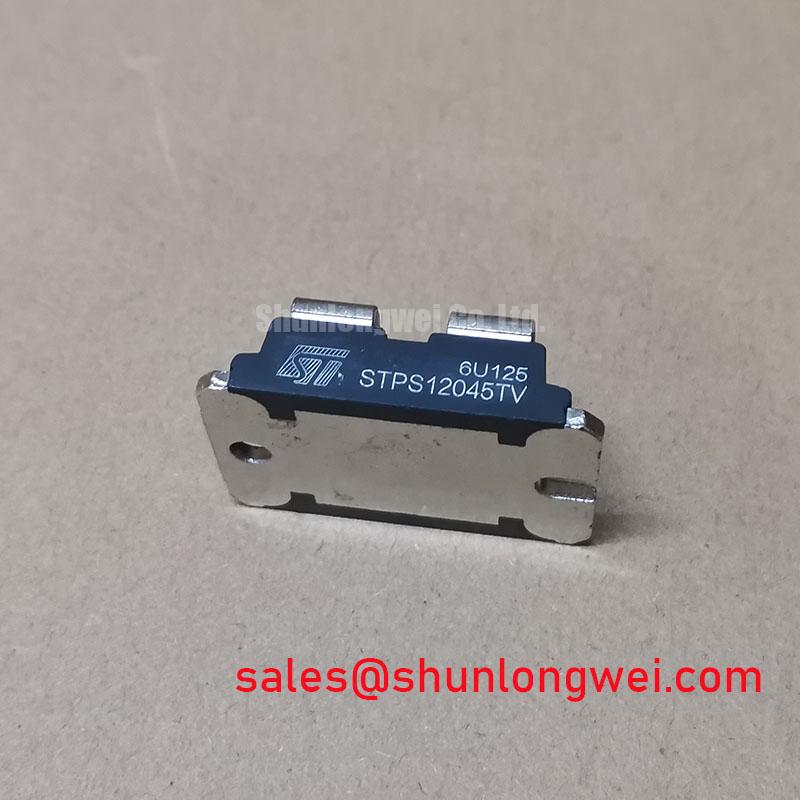
The STMicroelectronics STPS12045TV is a dual common-cathode power Schottky rectifier engineered for high efficiency in demanding power conversion circuits. Its core value proposition is the combination of an exceptionally low forward voltage drop and a high maximum junction temperature, which enables designers to minimize power loss and improve system reliability, especially in thermally sensitive applications.
- Core Specifications: 45V | 2 x 6A | VF (max) @ 125°C = 0.57V
- Key Engineering Benefits:
- Significantly reduces conduction losses for higher system efficiency.
- Robust high-temperature operation enhances reliability under heavy loads.
By minimizing the energy dissipated as heat, the STPS12045TV allows for more compact thermal management solutions, directly addressing the challenge of increasing power density. Download the Official STPS12045TV Datasheet (PDF)

Technical Analysis for Enhanced Performance
The engineering value of the STPS12045TV is rooted in its electrical and thermal characteristics. The maximum forward voltage drop (VF) per diode is specified at just 0.57V when conducting 6A at a junction temperature of 125°C. This parameter is critical because it directly dictates conduction losses (PCOND = VF × IF). A lower VF means less power is converted into waste heat, leading to higher overall efficiency and a cooler-running device. Think of VF as electrical friction; this device has exceptionally low friction, allowing current to pass with minimal energy loss.
Complementing its efficiency is its thermal robustness. The device is rated for a maximum operating junction temperature (Tj) of 175°C. This high thermal ceiling provides a substantial safety margin, ensuring reliable operation in elevated ambient temperatures or under conditions of high power dissipation. The low junction-to-case thermal resistance (Rth(j-c)) of 2.5 °C/W per diode ensures that the heat generated at the PN junction can be efficiently transferred to a heatsink. A proper thermal management strategy is key to leveraging this component’s full potential.

Optimized Application Scenarios
The specific characteristics of the STPS12045TV make it a strong candidate for several power applications:
- Switch-Mode Power Supplies (SMPS): Ideal for the output rectification stage, where its low VF directly boosts efficiency and reduces the size of required heat sinks.
- DC/DC Converters: The extremely fast switching capability and low losses support higher frequency designs, enabling smaller magnetic components and greater power density.
- Freewheeling & Polarity Protection: Used as a freewheeling diode, it protects switching elements from inductive voltage spikes with minimal energy loss. It is also highly effective for reverse polarity protection circuits.
- OR-ing Diodes: In redundant power supply systems, the low forward voltage drop minimizes voltage loss and power dissipation when combining multiple power sources.
This rectifier is best matched for high-frequency power circuits where minimizing conduction losses and ensuring thermal stability are primary design goals.
Key Electrical & Thermal Specifications
| Key Parameters for STPS12045TV | |
|---|---|
| Repetitive Peak Reverse Voltage (VRRM) | 45 V |
| Average Forward Current (IF(AV)) per diode, δ = 0.5 | 6 A |
| Forward Voltage Drop (VF) @ 6A, Tj=125°C (Max) | 0.57 V |
| Peak Reverse Current (IRM) @ VR=45V, Tj=125°C (Max) | 15 mA |
| Junction to Case Thermal Resistance (Rth(j-c)) per diode | 2.5 °C/W |
| Maximum Operating Junction Temperature (Tj) | -65 to +175 °C |
Note: Parameters are based on the official manufacturer’s datasheet. For complete details, refer to the document.
Engineer’s FAQ
- What is the primary benefit of the STPS12045TV’s low forward voltage drop?
- The primary benefit is higher energy efficiency. A lower forward voltage drop (VF) results in lower power dissipation (P = VF * IF) during conduction. This means less energy is wasted as heat, leading to a cooler device and a more efficient overall system, which is crucial in applications like high-frequency inverters.
- How do I calculate power dissipation for one diode in the STPS12045TV?
- To a first approximation, you calculate the conduction loss by multiplying the forward voltage drop (VF) from the datasheet’s curves (Figure 7) by the average forward current (IF(AV)) flowing through the diode in your application. For a more precise calculation, use the formula provided in the datasheet: P = 0.40 x IF(AV) + 0.028 x IF(RMS)². Always account for switching losses in high-frequency designs.
- What does the common cathode configuration mean for my circuit design?
- The common cathode configuration means the two internal diodes share a common negative terminal (the cathode, pin 2). The anodes (pins 1 and 3) are separate. This setup is ideal for creating a full-wave rectifier with a center-tapped transformer or for use as two independent rectifiers in applications like OR-ing, provided their cathodes are connected to the same potential.
- How does the 175°C maximum junction temperature impact thermal design?
- The high Tj provides a larger thermal operating margin. It allows the diode to function safely at higher ambient temperatures or to handle larger power dissipation before reaching its thermal limit. This robustness simplifies heatsink selection and can lead to more compact and cost-effective thermal solutions compared to rectifiers with lower temperature ratings.
By integrating a low forward voltage drop with high-temperature capability, the STPS12045TV enables engineers to develop more efficient, dense, and reliable power semiconductor solutions for a wide range of DC power applications.