NIEC PD10M440H: A High-Isolation Diode Module for Robust Power Rectification
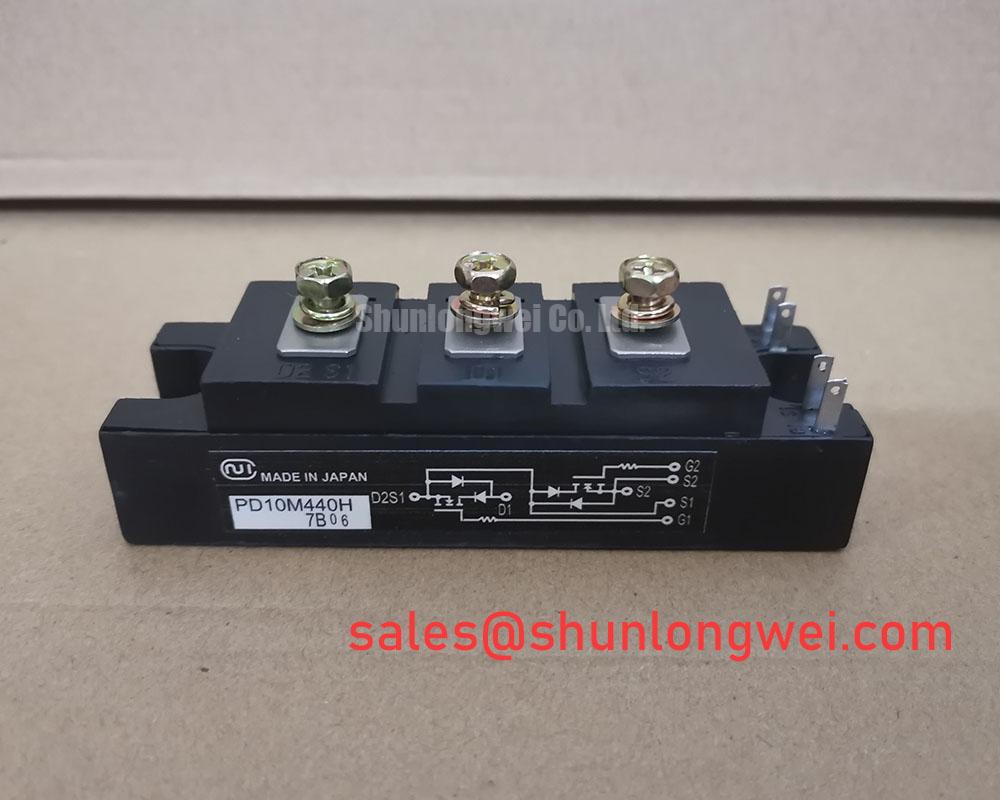
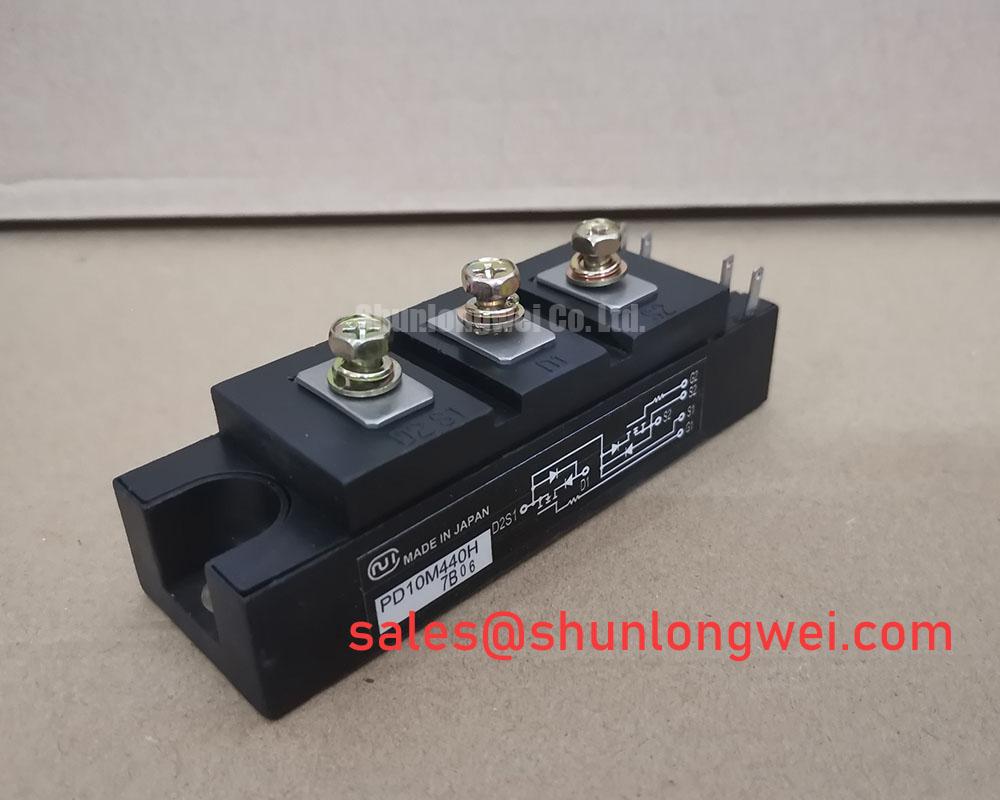
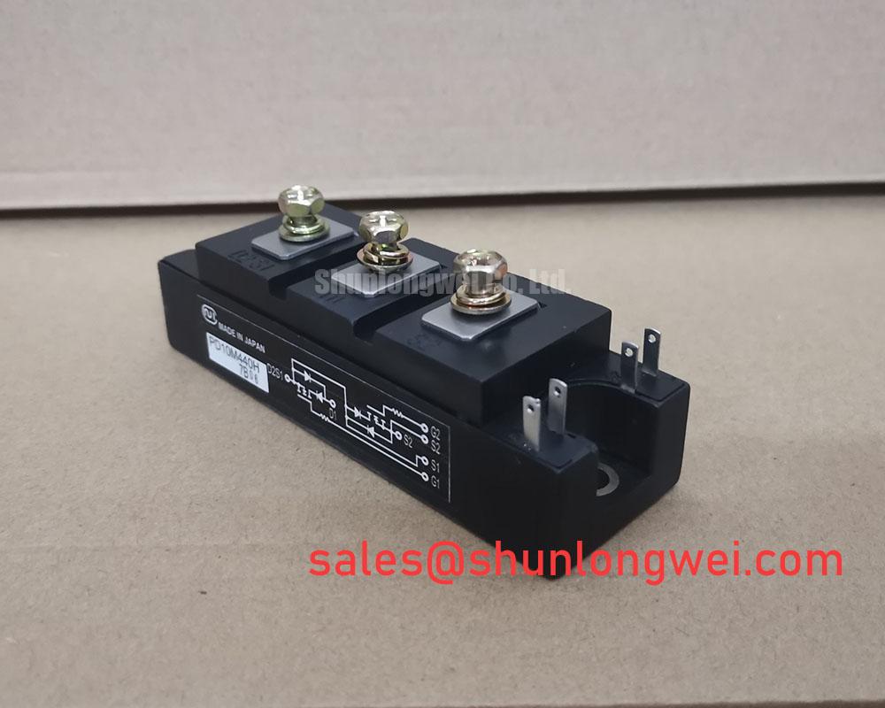
NIEC PD10M440H Diode Module for 400V/10A Rectification
Robust Power Control with High Electrical Isolation
The NIEC PD10M440H is a dual diode module that provides a robust and efficient solution for power rectification. Its defining feature is a high electrical isolation voltage, which simplifies system design and enhances operational safety. This module is engineered to deliver stable performance in a compact, industry-standard package for a variety of power conversion applications.
- Core Specifications: 400V | 10A | Viso 2500V
- Key Advantages: Simplifies thermal design with an electrically isolated mounting base. Provides high surge current capability for improved system ruggedness.
- Design Consideration: The 2500V isolation rating allows the module to be mounted directly to a grounded chassis or heatsink, removing the need for additional insulating materials and reducing assembly complexity.
Download Official Datasheet (PDF)
Technical Analysis of the NIEC PD10M440H Diode Module
The engineering value of the PD10M440H is centered on its electrical isolation and thermal performance. The module specifies an isolation voltage (Viso) of 2500V AC (for 1 minute), which is a critical safety and design feature. This high isolation allows engineers to mount the module’s metal baseplate directly to a shared heatsink or system chassis without using extra insulating pads. This approach not only streamlines the assembly process but also improves thermal conductivity compared to systems requiring separate insulation, leading to more effective cooling.
Effective thermal management is further supported by the module’s thermal resistance characteristic. The datasheet specifies a thermal resistance from junction-to-case (Rth(j-c)) of 3.6 °C/W per arm. This value can be thought of like the width of a pipe for heat transfer; a lower value indicates a wider pipe, allowing heat to escape the semiconductor junction more efficiently. This parameter is fundamental for calculating the necessary heatsink performance to ensure the junction temperature remains below the maximum rating of 150°C during operation.
Furthermore, the PD10M440H demonstrates considerable robustness with its non-repetitive peak forward surge current (IFSM) rating of 250A (for a 50Hz half-sine wave). This high surge capability ensures the module can withstand significant inrush currents during power-up or other transient fault conditions without failure. This resilience is a key factor in building reliable power systems, such as those discussed in guides on analyzing component failures.
Optimized Application Scenarios
The specific characteristics of the PD10M440H make it a strong candidate for several applications:
- General-Purpose Power Supplies: Well-suited for the input rectification stage of AC-DC converters, where its 400V rating provides sufficient headroom for many line voltage applications.
- Battery Charging Systems: The module’s efficiency and isolated base enhance the safety and reliability of charging circuits for industrial or consumer devices.
- Freewheeling Diode Applications: In DC motor drives and other inductive load switching circuits, it can serve as a freewheeling diode, safely dissipating stored energy. This is a core concept in power semiconductor applications.
- Inverter Welding Machines: The high surge current capability allows it to handle the demanding, pulsed-load conditions found in welding power sources.
This module is best suited for low-to-medium power applications where robust rectification, safety isolation, and a simplified thermal design are primary engineering goals.

Key Specifications of the NIEC PD10M440H
| Absolute Maximum Ratings (Ta = 25°C unless otherwise specified) | |
|---|---|
| Repetitive Peak Reverse Voltage (VRRM) | 400 V |
| Non-Repetitive Peak Reverse Voltage (VRSM) | 480 V |
| Average Forward Current (IF(AV)) | 10 A |
| Peak Forward Surge Current (IFSM) | 250 A (50Hz, half-sine) |
| Operating Junction Temperature (Tj) | -40 to 150 °C |
| Isolation Voltage (Viso) | 2500 V (AC, 1 minute) |
| Electrical & Thermal Characteristics (Tj = 25°C) | |
| Maximum Forward Voltage (VFM) | 1.3 V (at IFM = 10 A) |
| Repetitive Peak Reverse Current (IRRM) | 5 mA (at VRRM = 400 V) |
| Thermal Resistance, Junction to Case (Rth(j-c)) | 3.6 °C/W (Per Arm) |
Engineer’s FAQ
What is the main benefit of the 2500V isolation voltage on the PD10M440H?
The primary benefit is simplified thermal design. It allows the module to be mounted directly onto a grounded heatsink or chassis without requiring a separate, thermally impeding insulating layer. This reduces component count, lowers assembly costs, and can lead to more effective heat dissipation.
How should I properly mount this module to a heatsink?
Ensure the heatsink surface is clean and flat. Apply a thin, even layer of thermal compound. The datasheet specifies a mounting torque of 0.8 N·m for the module’s mounting holes. Adhering to this torque value is critical for ensuring optimal thermal contact without inducing mechanical stress on the module’s housing.
What is the internal configuration of the diodes?
The PD10M440H is a dual diode module. Based on the circuit diagram in the datasheet, the two diodes are internally connected in a common cathode configuration, with three terminals for the two anodes and the common cathode.
Can this module be used for high-frequency applications?
The datasheet does not provide detailed specifications for reverse recovery time (Trr), which is a key parameter for high-frequency switching performance. This module is primarily intended for line-frequency rectification (50/60 Hz). For high-frequency designs, a module with specified fast or ultra-fast recovery characteristics would be a more suitable choice. For further reading, see this guide on soft recovery diodes.
Enabling Simplified and Reliable Power Design
The NIEC PD10M440H Diode Module offers a practical solution for engineers tasked with designing robust power rectification circuits. By integrating high electrical isolation directly into the component, it addresses critical safety and assembly challenges, allowing design teams to focus on optimizing system performance and reliability.