Fuji 6MBP150VEA120-50 IPM: A Technical Review and Analysis
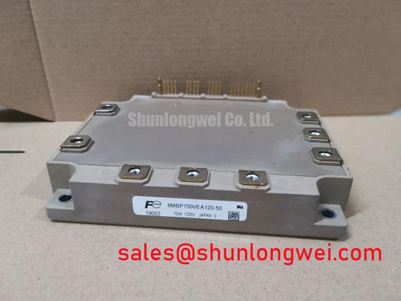
## Fuji 6MBP150VEA120-50 IPM | 1200V 150A V-Series Module
Introduction to the 6MBP150VEA120-50 Intelligent Power Module
The Fuji Electric 6MBP150VEA120-50 is a V-Series Intelligent Power Module (IPM) that integrates a full 6-pack IGBT array with optimized gate drivers and comprehensive protection circuits. This high level of integration provides a robust foundation for developing reliable and efficient three-phase inverter systems by simplifying design and accelerating time-to-market. The module leverages Fuji Electric’s V-Series IGBT technology to achieve a balance between low conduction losses and durable switching performance.
* **Core Specifications**: 1200V | 150A | 6-Pack Configuration
* **Key Advantages**: Simplifies thermal design with low thermal resistance and enhances system safety with integrated over-current, short-circuit, under-voltage, and over-temperature protections.
* **Design Efficiency**: Reduces component count and minimizes the complexities of PCB layout associated with discrete gate driver circuits.
For detailed electrical characteristics and thermal performance curves, refer to the official 6MBP150VEA120-50 datasheet (PDF).


Technical Analysis: Integration and Thermal Performance
The primary engineering advantage of the 6MBP150VEA120-50 lies in its high degree of integration. By co-packaging the gate drive circuitry with the power switches, it eliminates the intricate task of designing, routing, and protecting sensitive gate control signals. This integrated IPM structure inherently provides optimized switching characteristics and includes built-in protection against over-current (OC), short-circuit (SC), control voltage under-voltage (UV), and over-temperature (OT) events. This allows engineers to focus on system-level logic rather than discrete component-level protection, leading to a more robust and reliable final product.
Efficient thermal management is critical for high-power modules. The datasheet specifies a thermal resistance from junction to case (Rth(j-c)) of 0.16 °C/W for each IGBT and 0.28 °C/W for each freewheeling diode (FWD). Think of thermal resistance as the width of a pipeline for heat; a lower value indicates a wider pipe, allowing heat to escape more easily from the semiconductor die to the heatsink. These low thermal resistance values facilitate effective heat dissipation, enabling the module to operate reliably under demanding load conditions and potentially reducing the size and cost of the required cooling system. For detailed thermal calculations, engineers can use these values as a starting point for mastering IGBT thermal design.
Optimized Application Scenarios
The specific ratings and integrated features of this module make it a strong candidate for several power conversion applications:
* **General Purpose Inverters:** The module’s robust 1200V blocking voltage and 150A current rating are well-suited for industrial inverters driving motors up to the 75 kW class. The integrated protections provide the necessary resilience for demanding factory environments.
* **AC Servo Drives:** Precision motor control demands reliable and predictable switching. The optimized internal gate driver ensures consistent performance, while the module’s 6-pack topology forms a complete three-phase output stage.
* **Uninterruptible Power Supplies (UPS):** System reliability is paramount in UPS applications. The built-in OC, SC, UV, and OT protections significantly enhance the operational safety and longevity of the power stage.
* **Propulsion and Auxiliary Inverters:** The compact P629 package and integrated nature of the IPM are advantageous in space-constrained applications.
This module’s balance of current capacity, voltage rating, and integrated protection makes it an excellent fit for three-phase inverter designs demanding high reliability and a simplified assembly process.
Key Specifications of the 6MBP150VEA120-50
| Absolute Maximum Ratings | ||
|---|---|---|
| Parameter | Symbol | Value |
| Collector-Emitter Voltage | V_CES | 1200V |
| Collector Current (DC, Tc=25°C) | ±I_C | 150A |
| Collector Current (Peak, Tc=100°C) | ±I_CP | 300A |
| Collector Power Dissipation (per IGBT) | P_C | 781W |
| Operating Junction Temperature | T_j | -40 to +150°C |
| Electrical Characteristics (IGBT Inverter Part) | ||
| Collector-Emitter Saturation Voltage (Typ.) | V_CE(sat) | 1.70V (at 150A) |
| Diode Forward Voltage (Typ.) | V_F | 1.65V (at 150A) |
| Control Supply Voltage | V_CC | 15V (13.5V to 16.5V) |
| Thermal Characteristics | ||
| Thermal Resistance (Junction-to-Case, IGBT) | R_th(j-c)Q | 0.16 °C/W |
| Thermal Resistance (Junction-to-Case, FWD) | R_th(j-c)F | 0.28 °C/W |
Engineer’s FAQ for the 6MBP150VEA120-50
What is the primary benefit of the integrated protection features?
The integrated circuits provide comprehensive protection without needing external monitoring components. This module includes short-circuit (SC) protection, over-current (OC) protection by current sense emitters, control supply under-voltage (UV) lockout, and over-temperature (OT) protection through direct junction temperature detection. This simplifies the design and improves overall system robustness.
How do I implement thermal management for this IPM?
Effective thermal management starts with the module’s specified thermal resistance, R_th(j-c), of 0.16 °C/W per IGBT. To calculate the total heatsink requirement, you must sum this value with the thermal resistance of the thermal interface material (TIM) and the heatsink itself. The goal is to ensure the maximum junction temperature of 150°C is never exceeded under worst-case operating conditions. A flat, clean mounting surface is critical for optimal thermal transfer.
What are the control-side power supply requirements?
The datasheet specifies a control supply voltage (Vcc) of 15V for each of the three isolated supplies (for the upper and lower arms). The acceptable operating range is 13.5V to 16.5V. Operation outside this range may trigger the under-voltage lockout protection to prevent damage to the IGBTs. Each supply requires a typical current of 60mA.
Is there a difference between this IPM and a Power Integrated Module (PIM)?
Yes, while both offer integration, they serve different purposes. This IPM includes the power switches (IGBTs) and the intelligent gate drive and protection circuits. A PIM (Power Integrated Module) typically integrates multiple power stages, like a rectifier, brake chopper, and inverter, but may not include the gate drive and protection intelligence. The 6MBP150VEA120-50 is strictly an intelligent inverter stage.
Design and Reliability
The 6MBP150VEA120-50 enables engineers to build more compact and reliable power conversion systems. By integrating the core drive and protection functions into a single, thermally efficient package, this V-Series IPM reduces design complexity and enhances operational safety, empowering the development of high-performance inverters and motor drives.