Fuji 7MBR50SB120-55: An Integrated PIM for Compact Motor Drives
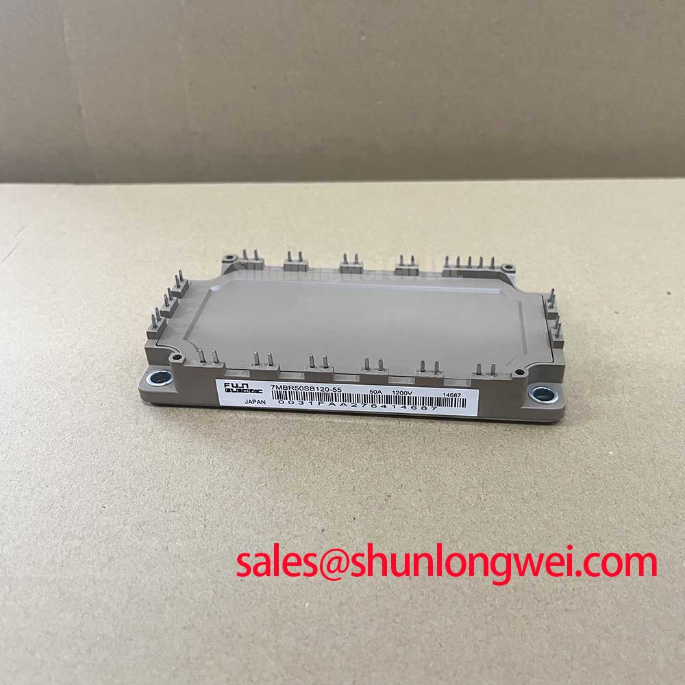
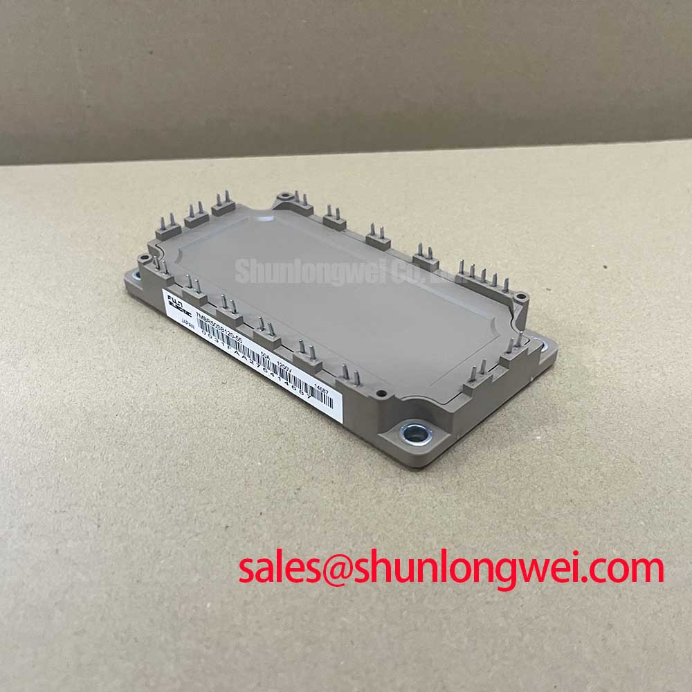
Fuji 7MBR50SB120-55 1200V/50A PIM IGBT Module
Integrated Power Stage for Compact Motor Drives
The Fuji Electric 7MBR50SB120-55 is a highly integrated 7-in-1 Power Integrated Module (PIM) that combines a three-phase converter, brake chopper, and a six-IGBT inverter into a single, compact, board-mountable package. This module provides a robust foundation for developing space-efficient and reliable motor drives and power converters. Its design focuses on simplifying system assembly and enhancing thermal performance.
- Core Specifications: 1200V | 50A | VCE(sat) 2.7V (max)
- Key Advantages: Reduces component count and simplifies PCB layout. An integrated NTC thermistor enables precise thermal protection.
This module’s architecture directly addresses the engineering challenge of building compact inverters without compromising on reliability. Download the reference datasheet (PDF) for detailed electrical characteristics and performance curves.
Technical Analysis: Integration and Thermal Management
The core value of the 7MBR50SB120-55 lies in its high level of integration. By combining the input rectifier bridge, brake chopper IGBT, inverter stage, and a freewheeling diode for the brake circuit into one component, it offers a significant advantage over discrete solutions. This approach minimizes parasitic inductance between stages, a common source of voltage overshoot and EMI in power systems. For designers, this means a more straightforward layout and potentially a reduced need for extensive snubber circuits, as explored in discussions around PIM vs. discrete IGBT strategies.
Efficiently managing heat is critical in a compact module. The thermal resistance from junction to case (Rth(j-c)) for the inverter IGBT is specified as 0.34°C/W per device. This parameter can be imagined like the width of a pipe meant for heat to escape; a lower value indicates a wider, more effective path for heat to travel from the silicon die to the heatsink. This allows for either a smaller cooling apparatus or higher operational reliability at a given load. The inclusion of an integrated NTC thermistor provides the direct temperature feedback necessary for implementing robust over-temperature protection.

Optimized Application Scenarios
The specific characteristics of this module make it a strong candidate for several applications:
- Small to Medium Motor Drives: Its 50A rating is well-suited for three-phase AC motors up to approximately 11-15 kW. The all-in-one design drastically cuts down assembly time and system size.
- AC and DC Servo Drive Amplifiers: The fast switching times (ton typ. 0.35µs, toff typ. 0.45µs) and integrated brake chopper are essential for the dynamic torque control required in servo systems.
- Uninterruptible Power Supplies (UPS): The robust 1200V rating provides a sufficient safety margin for applications connected to 380V-480V AC lines, while the integrated nature of the module improves the power density of the UPS unit.
This module is best matched for systems where reducing size and simplifying manufacturing are primary engineering goals without sacrificing thermal oversight.
Key Specifications of the 7MBR50SB120-55
| Parameter | Value | Component |
|---|---|---|
| Collector-Emitter Voltage (VCES) | 1200 V | Inverter & Brake IGBT |
| Collector Current (IC) at Tc=80°C | 50 A (Inverter) / 25 A (Brake) | IGBT |
| Collector-Emitter Saturation Voltage (VCE(sat)) at nominal IC | 2.7 V (Max) | Inverter IGBT |
| Repetitive Peak Reverse Voltage (VRRM) | 1600 V | Converter Diode |
| Average Output Current (IO) | 50 A | Converter Diode |
| Maximum Junction Temperature (Tj) | 150 °C | – |
| Isolation Voltage (Viso) | AC 2500 V (1 minute) | – |


Engineer FAQ
What does the ‘7-in-1’ topology of the 7MBR50SB120-55 include?
The module contains a three-phase input rectifier (6 diodes), a brake chopper (1 IGBT with a parallel freewheeling diode), and a three-phase output inverter (6 IGBTs with 6 freewheeling diodes). It also includes an NTC thermistor for temperature sensing.
What are the key considerations for thermal design with this PIM?
The primary goal is to ensure the junction temperature (Tj) remains below the 150°C maximum rating. To do this, calculate the total power loss (conduction and switching) for your specific operating conditions. Use the thermal resistance Rth(j-c) of 0.34°C/W for the inverter IGBT and 0.65°C/W for the inverter FWD to select a heatsink that can dissipate this power effectively. A guide on mastering IGBT thermal design can provide further context.
What is the recommended gate drive voltage?
The datasheet specifies characteristics at a gate-emitter voltage (VGE) of +/-15V. A positive voltage of +15V is standard for turn-on. Using a negative voltage of -8V to -15V for turn-off is recommended to prevent parasitic turn-on events caused by high dv/dt, ensuring more robust switching performance.
What is the function of the brake circuit?
The integrated brake chopper is used to dissipate regenerative energy from the motor during deceleration. When the motor acts as a generator, it feeds energy back to the DC bus, causing the voltage to rise. The brake circuit switches this excess energy into an external braking resistor, protecting the module from overvoltage conditions.
Enabling Efficient and Compact Power Conversion
The Fuji 7MBR50SB120-55 is a comprehensive power stage that empowers engineers to reduce design complexity and shrink the footprint of motor drives and UPS systems. By integrating the core components of a three-phase inverter system into a single, thermally-aware module, it facilitates the creation of more reliable and cost-effective end products. Its balanced electrical characteristics provide a solid basis for efficient power semiconductor designs.