Fuji 6MBI10L-060: A Technical Review of the 6-in-1 Integrated Power Module
“`html
Fuji 6MBI10L-060 IGBT Module: 600V, 10A 6-in-1 Power Stage
Introduction and Core Highlights
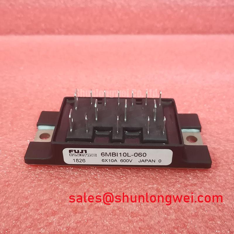
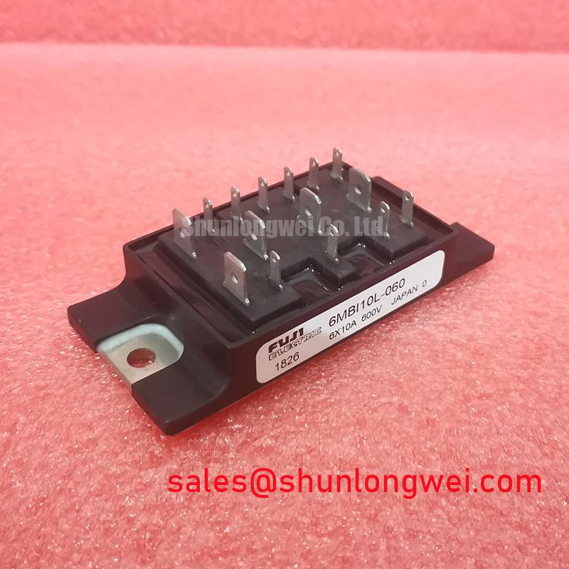
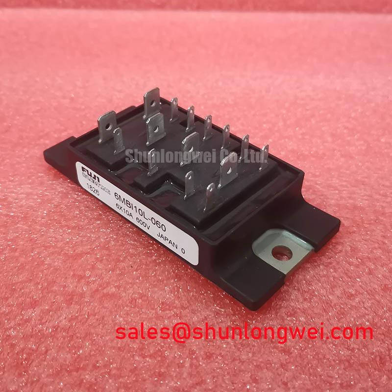
The Fuji Electric 6MBI10L-060 is an IGBT module that integrates a complete three-phase inverter bridge into a single, compact package. This 6-in-1 configuration is its defining engineering advantage, providing a streamlined solution for low-power motor control and inverter applications by significantly reducing component count and simplifying PCB layout. It offers a well-balanced set of electrical and thermal characteristics for reliable performance.
- Core Specifications: 600V | 10A | 6-in-1 Configuration
- Key Engineering Advantages: Simplifies three-phase power stage design, reduces overall system footprint.
- Primary Application Focus: Excellent fit for fractional horsepower motor drives where space and assembly efficiency are primary design drivers.
Download the Official 6MBI10L-060 Datasheet (PDF)
Technical Analysis of the Integrated Design
The primary value of the 6MBI10L-060 lies in its high level of integration. By housing six IGBTs and six corresponding free-wheeling diodes (FWDs) in one module, it forms a complete B6-bridge for three-phase applications. For design engineers, this approach replaces twelve or more discrete components. The immediate benefits include a drastically simplified schematic, reduced PCB routing complexity, and minimized parasitic inductance between components, which is a common challenge in high-frequency power stages. This integration accelerates the assembly process and reduces potential points of failure.
From a performance standpoint, the module’s collector-emitter saturation voltage (VCE(sat)) is a critical parameter for thermal design. Specified at a maximum of 2.8V at a junction temperature of 125°C, this value dictates the conduction losses during operation. You can think of VCE(sat) as a form of electrical friction; a lower value means less energy is wasted as heat when the switch is on. This parameter is essential for calculating the total power dissipation and selecting an appropriate heatsink to maintain the junction temperature within its safe operating limits.
Optimized Application Scenarios
The specific ratings and integrated topology of this module make it a strong candidate for several applications:
- Small Motor Drives: Its 10A continuous current rating is well-suited for driving fractional horsepower AC motors in applications like conveyors, pumps, and fans. The integrated bridge simplifies the inverter design significantly.
- AC Servo Systems: The module provides the necessary switching components for precise position and speed control in low-power servo applications.
- General-Purpose Inverters: For systems converting DC power to a low-power three-phase AC output, the 600V rating provides a safe margin for operation on 200-240V AC lines.
- HVAC Systems: The power level is appropriate for controlling compressor or fan motors in residential air conditioning units, where compact design is often valued.
This module is best matched for inverter designs under 4kW requiring a compact, reliable, and easy-to-integrate power stage.
Key Specifications of the 6MBI10L-060
| Absolute Maximum Ratings (at Tc = 25°C unless otherwise specified) | |
|---|---|
| Collector-Emitter Voltage (VCES) | 600V |
| Gate-Emitter Voltage (VGES) | ±20V |
| Continuous Collector Current (IC) | 10A (at Tc = 80°C) |
| 1ms Collector Current (IC pulse) | 20A |
| Max Power Dissipation (Pc) | 50W per IGBT |
| Operating Junction Temperature (Tj) | +150°C |
| Electrical & Thermal Characteristics (Per IGBT/FWD, at Tj=25°C) | |
| Collector-Emitter Saturation Voltage (VCE(sat)) (Max, at 10A, Tj=125°C) | 2.8V |
| FWD Forward Voltage (VF) (Max, at 10A, Tj=125°C) | 2.4V |
| Thermal Resistance, Junction to Case (Rth(j-c)) (IGBT) | 2.5 °C/W |
| Thermal Resistance, Junction to Case (Rth(j-c)) (FWD) | 3.5 °C/W |
Engineer’s FAQ
What are the recommended mounting procedures for the 6MBI10L-060?
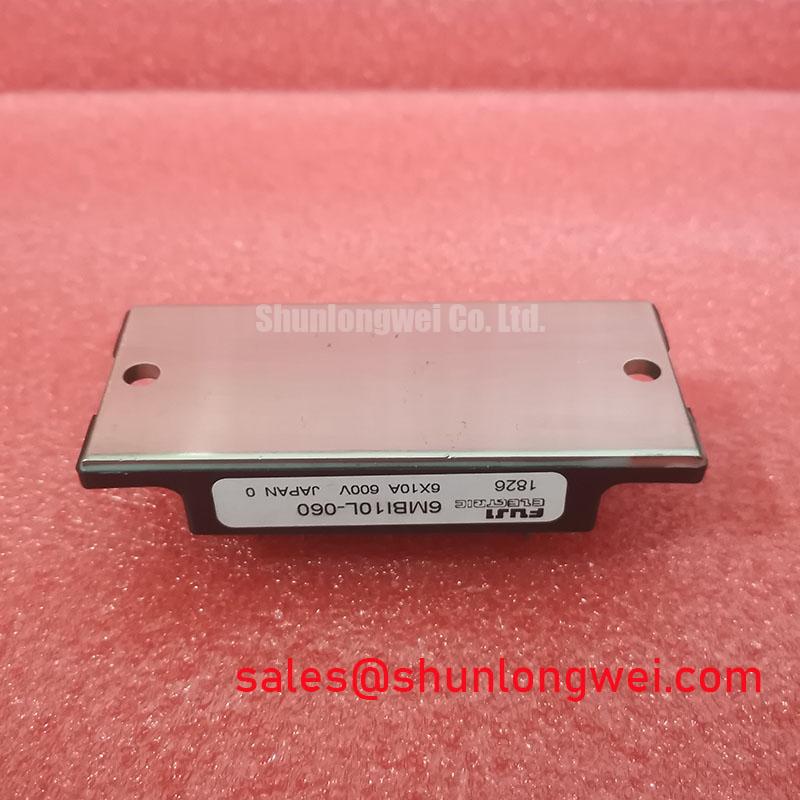
To ensure proper thermal transfer, apply a thin, even layer of thermal grease between the module’s baseplate and the heatsink. The module should be secured using M4 screws with a recommended tightening torque between 1.5 and 1.9 N·m. Uneven or excessive torque can lead to poor thermal contact or damage the module’s baseplate.
What is the benefit of the integrated Free-Wheeling Diode (FWD)?
The integrated FWD is essential for motor drive applications. When an IGBT turns off, the inductive energy stored in the motor windings must be dissipated safely. The FWD provides a path for this current to “freewheel,” preventing large voltage spikes that could damage the IGBTs. Learn more about the critical role of free-wheeling diodes in system performance.
Is this module suitable for high-frequency switching?
The 6MBI10L-060 is optimized for the moderate PWM frequencies typically used in motor control (e.g., up to ~15-20 kHz). While it can be used in other switching applications, its turn-on and turn-off energy losses (Eon, Eoff) should be carefully evaluated for higher frequency designs, as they will significantly contribute to overall power dissipation and heat generation.
Enabling Compact Power Conversion
The 6MBI10L-060 delivers a practical and reliable solution for engineers tasked with designing space-constrained, low-power three-phase systems. By consolidating the entire power bridge into a single module, it directly addresses the need for faster assembly, reduced design complexity, and a smaller final product footprint without compromising on the fundamental power semiconductor performance required for efficient motor control.
“`