FZ750R65KE3: Infineon’s 6.5kV 750A IGBT Module for High-Voltage Isolation and Thermal Reliability
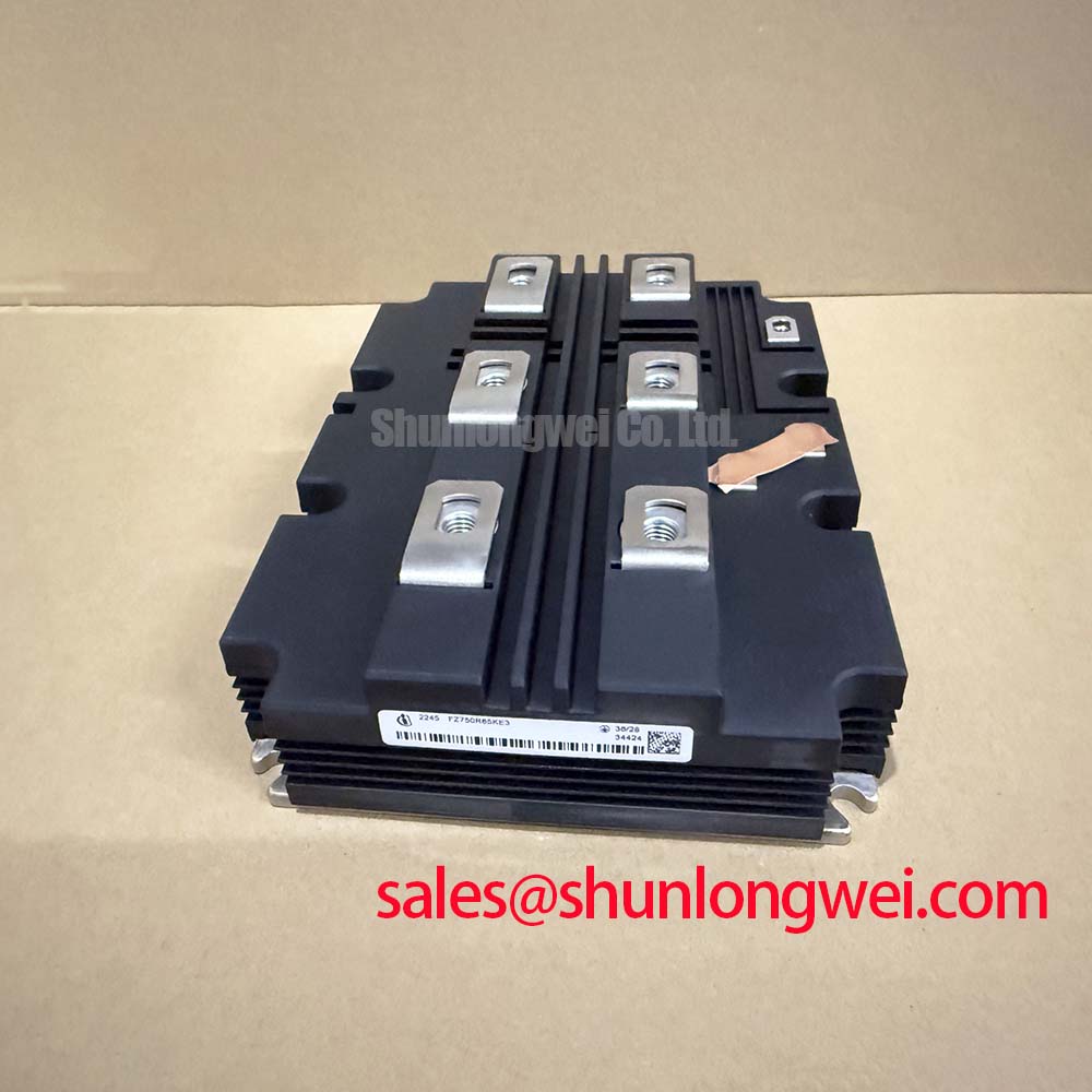
FZ750R65KE3 Infineon 6.5kV 750A IHM-B IGBT Module
Exceptional High-Voltage Isolation and Thermal Stability
The FZ750R65KE3 is a high-performance 6.5kV, 750A single IGBT module engineered with Infineon TRENCHSTOP™ IGBT3 technology and the EmCon3 diode. This component is optimized for megawatt-class power systems requiring extreme voltage insulation and long-term mechanical reliability. By utilizing an AlSiC baseplate, the module offers superior thermal cycling capability and mechanical robustness, addressing the core challenges of high-voltage IGBT implementations in railway traction and grid infrastructure.
- Core Specifications: 6500V | 750A | VCE(sat) 3.0V (typical at 125°C)
- Key Advantages: 10.2kV AC 1 min insulation rating and enhanced power density through the IHM-B package.
- Engineering Intent: The module answers the critical requirement for reduced conduction losses while maintaining a safe operating area in harsh electrical environments.
Download Official FZ750R65KE3 Datasheet (PDF)
Technical Analysis of Trenchstop™ IGBT3 and AlSiC Integration
The FZ750R65KE3 distinguishes itself through the synergy of its silicon technology and package materials. The Trenchstop™ IGBT3 architecture allows for a significantly lower VCE(sat) compared to previous generations, which translates directly to higher efficiency in high-power conversion. In large-scale converters, even a fractional reduction in saturation voltage prevents cumulative heat build-up that could compromise the Safe Operating Area (SOA) of the system.
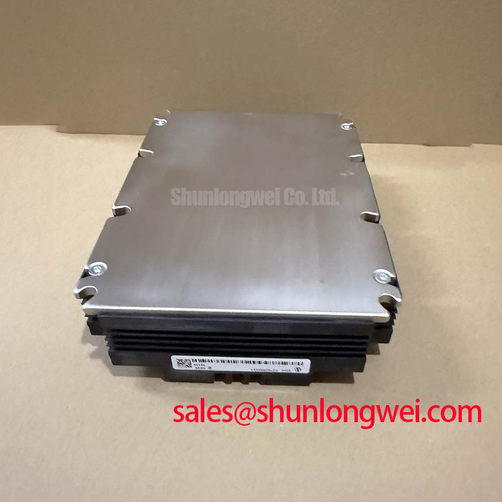
A pivotal feature is the AlSiC (Aluminum Silicon Carbide) baseplate. You can visualize the baseplate’s role as a thermal shock absorber; because its coefficient of thermal expansion is closely matched to the internal ceramic substrates, it minimizes the mechanical stress during rapid power cycling. This effectively prevents the delamination of internal layers, a common root cause analyzed in IGBT failure reports. The 10.2kV insulation rating further ensures that the module can withstand the significant potential differences found in traction and HVDC topologies without dielectric breakdown.
Optimized Application Scenarios
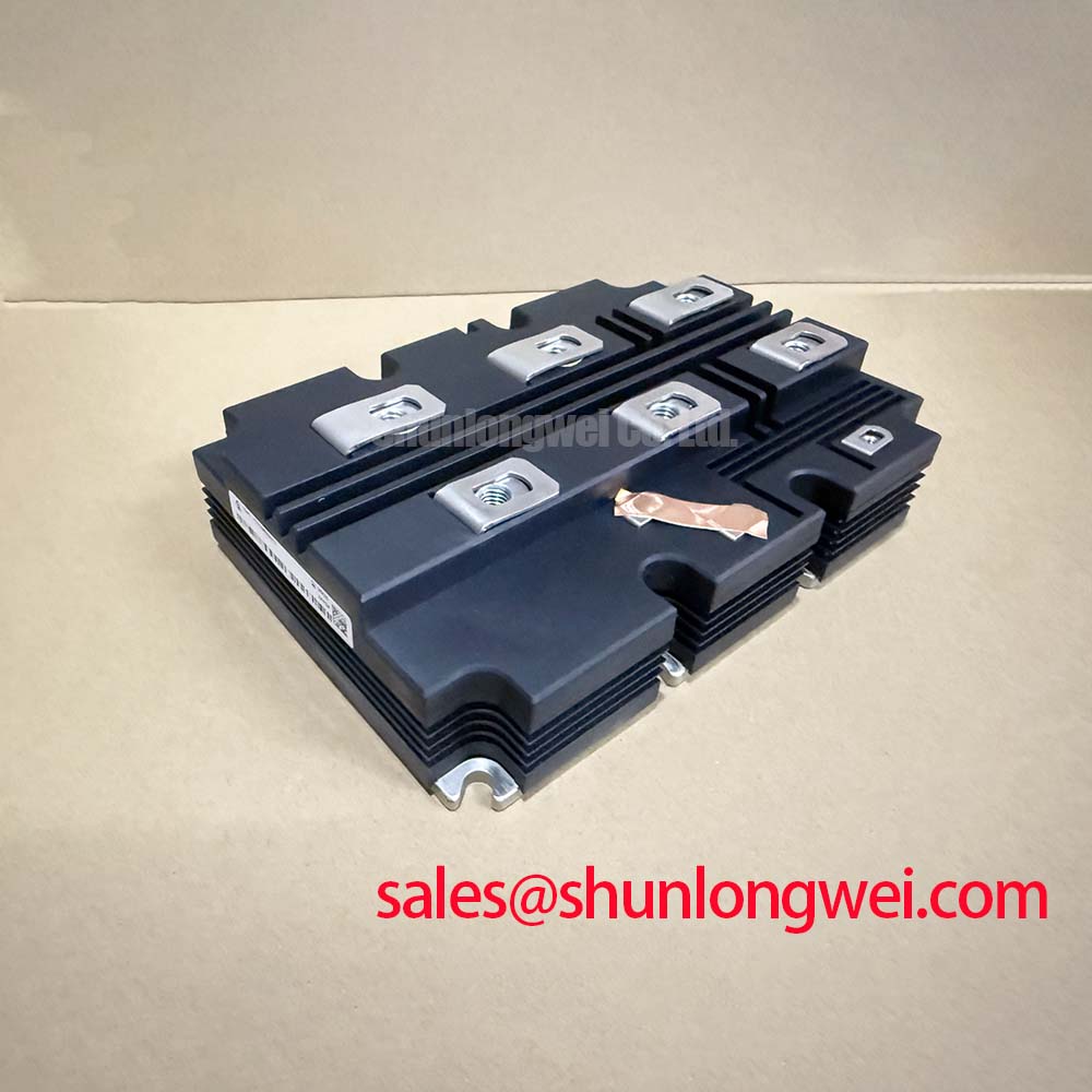
The FZ750R65KE3 is specifically characterized for environments where electrical clearance and thermal fatigue are the primary design constraints. The datasheet validates its performance in the following sectors:
- Railway Traction: Its AlSiC baseplate and high insulation make it the optimal choice for the demanding load profiles and vibration levels of electric locomotives.
- Medium Voltage Drives: Provides the necessary voltage headroom for industrial Variable Frequency Drives (VFDs) operating at 3.3kV and 4.16kV levels.
- HVDC and Grid Systems: The 6.5kV rating simplifies series stacking in megawatt power converters, reducing the total component count.
Best Matching: Ideally suited for converters requiring a 6.5kV rating with a strict requirement for 10.2kV isolation and high thermal cycling reliability.
Key Specifications Table
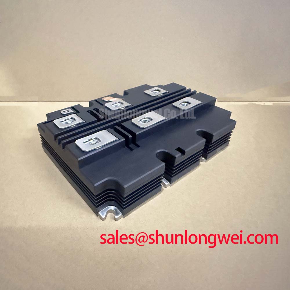
| Parameter Group | Specification | Value |
|---|---|---|
| Absolute Maximum Ratings | Collector-Emitter Voltage (VCES) | 6500 V |
| Continuous DC Collector Current (IC) | 750 A (at Tc=80°C) | |
| Isolation Test Voltage (VISOL) | 10.2 kV (RMS, f=50Hz, 1 min) | |
| Electrical Characteristics | IGBT Saturation Voltage (VCE sat) | 3.00 V (typ, Tvj=125°C) |
| Gate Threshold Voltage (VGE th) | 5.4 V – 6.6 V | |
| Thermal Characteristics | Thermal Resistance (RthJC – IGBT) | 11.0 K/kW |
| Operating Junction Temp (Tvj op) | -40°C to 125°C |
Engineer’s FAQ for FZ750R65KE3
1. What is the impact of the 10.2kV isolation voltage on system design?
The 10.2kV rating provides the dielectric strength required for applications with high pollution degrees or where the DC link voltage reaches levels that would cause standard 3.3kV or 4.5kV modules to fail. This high rating simplifies the requirement for additional external insulation barriers.
2. How does the AlSiC baseplate improve thermal cycling reliability?
Standard copper baseplates have a thermal expansion coefficient much higher than ceramic substrates, leading to solder fatigue over time. AlSiC matches the substrate expansion more closely, resulting in significantly higher power cycling counts before reaching wear-out limits.
3. What are the recommended gate drive conditions for switching 750A at 6.5kV?
According to the datasheet, the gate charge is 55.0 µC. To minimize switching losses and prevent EMI issues, intelligent gate drivers with active clamping are often utilized to manage the high dV/dt and dI/dt inherent to 6.5kV switching.
The FZ750R65KE3 enables engineers to achieve high-density power conversion in the most demanding voltage classes. Its combination of Trenchstop™ IGBT3 technology and AlSiC baseplate materials provides the necessary foundation for robust, efficient, and long-lasting industrial and traction power systems.