Mitsubishi PM30RSF060: Technical Guide to the 600V 30A Intelligent Power Module (IPM)
Mitsubishi PM30RSF060 Intelligent Power Module (IPM) | 600V 30A Inverter Bridge
High-Integration Power Stage with Built-In Protection Logic
The PM30RSF060 is a high-performance Intelligent Power Module (IPM) from Mitsubishi, engineered for 3-phase AC inverter applications requiring a built-in brake chopper. This module integrates high-speed, low-loss IGBT chips with optimized gate drive circuitry and a comprehensive protection suite. By combining the power stage and the driver logic into a single isolated package, the PM30RSF060 significantly reduces electromagnetic interference (EMI) and simplifies the design-in process for complex motor control systems.
- Core Ratings: 600V | 30A | Integrated Brake Chopper
- Integrated Logic: High-side and low-side gate drivers with fault feedback.
- Protection Suite: Over-temperature, short-circuit, and under-voltage lockout logic.
Download Official PM30RSF060 Datasheet (PDF)
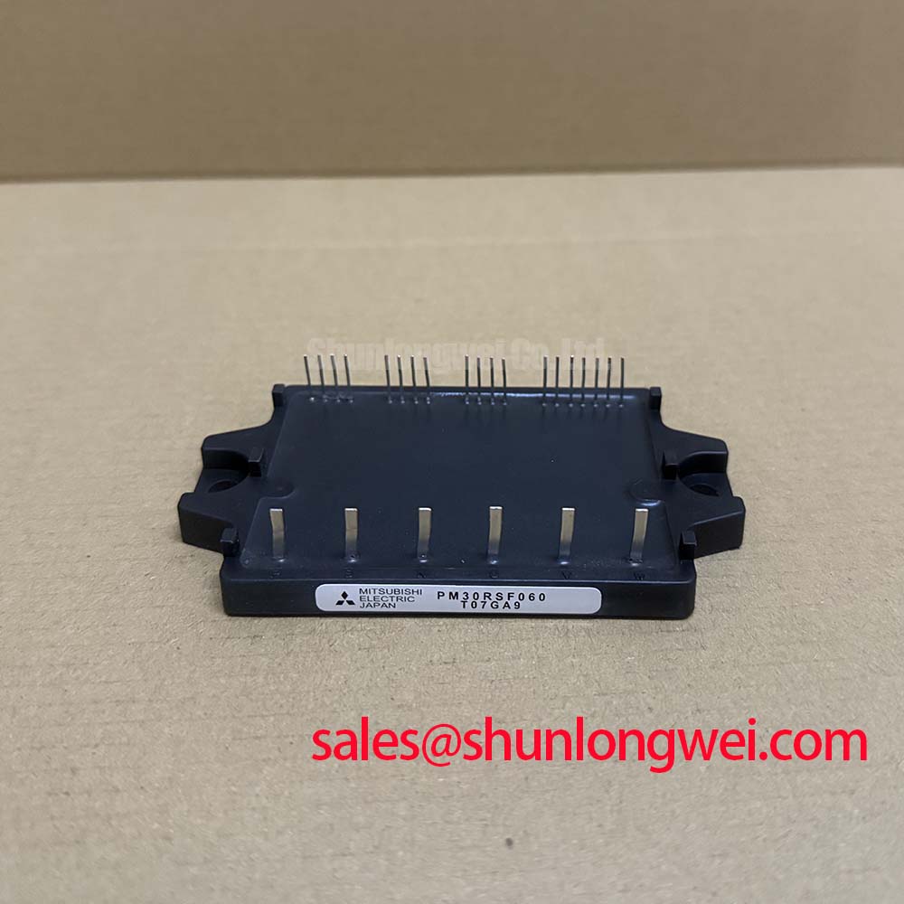


Technical Analysis: Precision Control via System Integration
The engineering value of the PM30RSF060 lies in its “Reflex-Action” protection. Unlike discrete setups where a fault must travel to an external controller before action is taken, this module monitors its own health in real-time. If the collector current exceeds the short-circuit threshold ($S_C$), the internal logic initiates a controlled shutdown within microseconds, independent of the external system controller. This local intelligence acts like a biological reflex, shielding the silicon from catastrophic failure before the main processor even detects the anomaly.
Thermal management is another critical area where the PM30RSF060 excels. The module features a built-in Over-Temperature (OT) sensor on the insulated baseplate. You can imagine thermal resistance ($R_{th}$) as the diameter of a drainage pipe; a lower value allows the “water” (heat) to escape more efficiently. By integrating the sensor directly into the module’s thermal path, the integrated NTC provides much higher accuracy than external thermistors, preventing localized hotspots that are common in high-density power converters.
Furthermore, the drive logic is optimized for high-speed switching with minimal parasitic inductance. Because the gate driver is millimeters away from the IGBT die, the gate loop area is minimized. This structural advantage reduces ringing and voltage spikes during turn-off, which is often a root cause of EMI issues and IGBT failures in industrial environments. Using intelligent IGBT drivers internal to the module ensures that the gate charge ($Q_G$) is delivered with precise timing, balancing switching losses ($E_{on}/E_{off}$) against harmonic distortion.
Optimized Application Scenarios
- General Purpose Inverters: Ideal for Variable Frequency Drives (VFD) where the integrated brake chopper facilitates rapid deceleration of motor loads.
- Servo Motor Control: The low $V_{CE(sat)}$ (typically 1.8V at 30A) ensures high torque efficiency and reduced cooling requirements in precision motion control.
- Small Capacity UPS: Robust short-circuit protection provides high system reliability during unexpected load surges.
- Air Conditioning Compressors: Compact flat-base packaging allows for slim-profile thermal designs in domestic and industrial HVAC systems.
Best Match: High-duty cycle motor applications where space-constrained thermal design and rapid fault response are non-negotiable engineering requirements.
PM30RSF060 Key Specifications
| Category | Parameter | Value (Typ/Max) |
|---|---|---|
| Maximum Ratings | Collector-Emitter Voltage ($V_{CES}$) | 600V |
| Collector Current ($I_C$) | 30A | |
| Isolation Voltage ($V_{iso}$) | 2500 Vrms (60Hz, 1 min) | |
| Electrical Characteristics | $V_{CE(sat)}$ (Inverter) | 1.8V (Typ) @ $I_C=30A$ |
| Switching Time ($t_{off}$) | 2.0 $mu$s (Max) | |
| Brake Diode Forward Voltage ($V_{FM}$) | 2.2V (Max) | |
| Thermal/Protection | Thermal Resistance ($R_{th(j-c)Q}$) | 0.95 $^circ$C/W (per IGBT) |
| Short Circuit Trip Level | 45A (Min) |
Engineer FAQ
Q1: What are the recommended isolation practices for the PM30RSF060 heatsink?
A: The module is internally isolated to 2500 Vrms. However, to maintain thermal performance, a high-quality thermal interface material (TIM) or silicone gel should be applied thinly and evenly. Over-tightening the mounting screws can warp the baseplate; refer to the datasheet for the specific torque rating (typically 2.5 ~ 3.5 N·m).
Q2: How does the “Fo” fault output signal behave during an error?
A: The Fo pin pulls low when the internal logic detects an Over-Temperature (OT), Short-Circuit (SC), or Under-Voltage (UV) condition. This signal is maintained for a specific pulse duration (typically 1.8ms) to allow the master controller to register the fault and stop the PWM signals safely.
Q3: Is negative gate voltage required for robust turn-off in the PM30RSF060?
A: No. Because the gate driver is integrated and optimized for the internal IGBT characteristics, the PM30RSF060 is designed to operate reliably with a single-sided power supply (typically 15V). The internal circuit handles the parasitic Miller effect to prevent unwanted turn-on without the need for a negative bias supply.
The PM30RSF060 provides a technically sound path for engineers to achieve high power density and protection reliability. By centralizing power switching and fault diagnostics into a single unit, it addresses the fundamental trade-offs between switching speed, thermal management, and EMI suppression.