FZ1200R33KF2C: Technical Overview of the 3300V 1200A High-Power IGBT Module
FZ1200R33KF2C: 3300V 1200A High-Power Single IGBT Module
Introduction and Core Technical Highlights
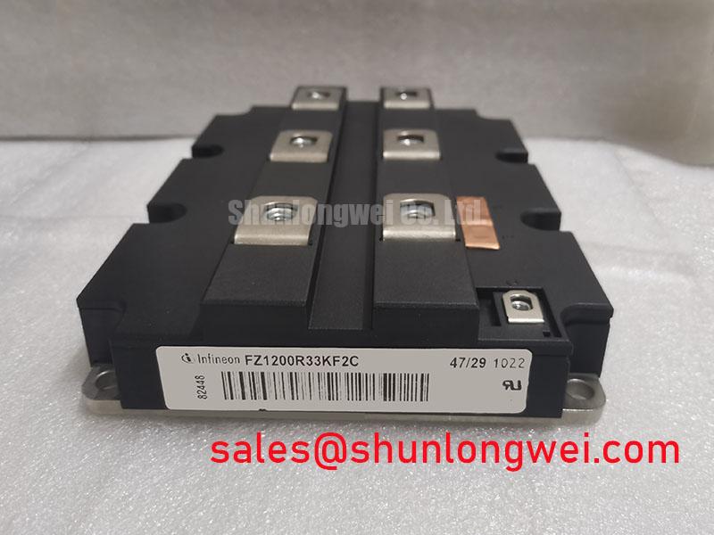
The FZ1200R33KF2C is an industry-standard, traction-grade single IGBT Module housed in a highly robust 130mm footprint. Engineered for demanding electrical and environmental conditions, this module features a 3300V blocking voltage and a nominal collector current of 1200A. Power electronics engineers evaluating this component often seek to optimize gate driver timing and calculate precise junction temperature swings under transient loads. The FZ1200R33KF2C addresses these thermal challenges directly with an integrated isolated copper baseplate and optimized thermal interface paths.
- Key Specifications: 3300V blocking voltage | 1200A continuous DC collector current (at TC = 80°C) | 4.30V typical VCE(sat) (at Tj = 125°C).
- Engineering Benefits: Reduces overall cooling system volume and simplifies symmetrical high-power paralleling schemes.
Download Official Manufacturer Datasheet (PDF)

Technical Analysis and Packaging Architecture
The internal architecture of the FZ1200R33KF2C utilizes advanced field-stop trench gate designs to strike a balance between on-state conduction losses and switching energy. To protect internal silicon dies from moisture and high-voltage breakdown, the package relies on specialized silicone gel insulation. This gel provides stable dielectric performance even under rapid temperature changes. The module is built on an isolated baseplate layout that delivers 6.0 kV RMS isolation voltage, simplifying safety compliance for medium-voltage system designs.


Thermal management is critical when operating at megawatt scales. You can think of thermal resistance ($R_{thJC}$) as a thermal highway: a lower resistance value acts like a wider highway, allowing heat generated at the silicon junctions to exit quickly to the external heatsink. The FZ1200R33KF2C achieves a highly competitive junction-to-case thermal resistance of 8.3 K/kW for the IGBT switch, ensuring that the silicon operating temperature remains stable under harsh duty cycles.
High switching speeds can create significant voltage spikes if layout parasitics are not controlled. Designers must minimize parasitic inductance in the DC-link busbar to prevent exceeding the limits of the device’s RBSOA (Reverse Bias Safe Operating Area). Implementing symmetrical gate paths and selecting optimal gate resistors will keep transient voltages safely within specifications during high-current turn-off events.
Target Application Environments
- Railway Traction Systems: Serves as the primary power switch in main traction inverters, providing reliable acceleration profiles.
- Industrial Medium-Voltage Drives: Regulates speed and torque in heavy-duty compressors, pumps, and metal extrusion machinery.
- Wind Turbine Converters: Converts variable wind energy to grid-synchronized AC with minimal thermal overhead.
- **Grid-Tie Solar Inverters:** Functions in central megawatt-scale PV converters where low conduction losses are critical for yield optimization.
Best Fit: Ideal for high-voltage, high-reliability infrastructure systems demanding long term thermal cycling stability and maximum load capacity.
Key Electrical and Thermal Specifications
| Parameter | Symbol | Test Conditions / Limits | Value |
|---|---|---|---|
| Collector-Emitter Voltage | VCES | Tvj = 25°C | 3300 V |
| Continuous DC Collector Current | IC | TC = 80°C, Tvj max = 150°C | 1200 A |
| Collector-Emitter Saturation Voltage | VCE(sat) | IC = 1200A, VGE = 15V, Tvj = 125°C | 4.30 V (typical) |
| Repetitive Peak Collector Current | ICRM | tp = 1 ms | 2400 A |
| Total Power Dissipation | Ptot | TC = 25°C, Tvj = 150°C | 15.0 kW |
| Isolation Test Voltage | VISOL | RMS, f = 50 Hz, t = 1 min | 6.0 kV |
| IGBT Thermal Resistance | RthJC | Junction-to-case, per module | 8.3 K/kW |
Engineer FAQ
Q: What is the maximum junction temperature limit under switching operation?
A: The FZ1200R33KF2C is rated for a maximum junction temperature ($T_{vj max}$) of 150°C, but standard switching operation is limited to $T_{vj} = 125°C$ to ensure long-term thermal cycling reliability.
Q: How should the gate driver be configured to prevent parasitic turn-on?
A: To counter transient Miller currents during high dV/dt events, engineers should use a driver with a negative gate bias (typically -15V) and implement active clamping or Miller clamp functionality near the module’s gate terminals.
Q: Why is silicone gel preferred over other encapsulation materials in this design?
A: Silicone gel offers excellent self-healing properties and maintains its breakdown strength over a wide temperature range. This is essential for protecting the 3300V dies from partial discharge and moisture ingress in high-altitude or outdoor rail environments.
Conclusion
The FZ1200R33KF2C high-power IGBT module represents a highly reliable solution for high-voltage, high-current power conversion platforms. Its combinations of a 3.3 kV blocking voltage, high isolation capability, and low internal thermal resistance provide engineers with the safety margins and thermal efficiency required to design robust locomotives and heavy industrial systems. For procurement and design-in evaluation, please refer strictly to the verified parameters outlined in the original manufacturer data sheet.