Fuji Electric 6MBP100KB060 600V 100A IGBT-IPM: Technical Overview and Design Guide
Fuji Electric 6MBP100KB060 600V 100A IGBT-IPM Module
Product Overview and Unique Engineering Value
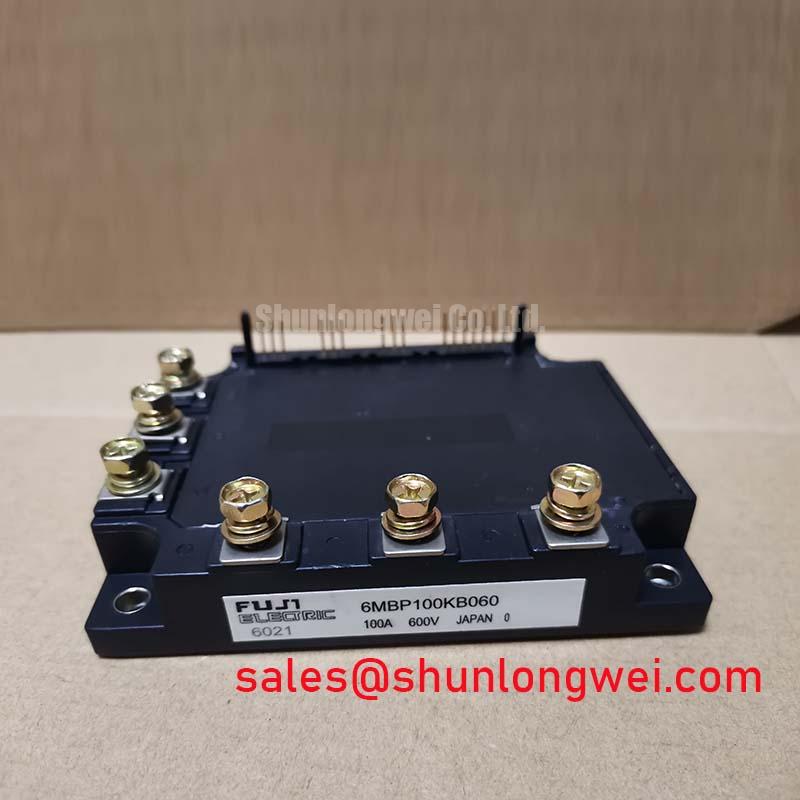
The Fuji Electric 6MBP100KB060 is an insulated-gate bipolar transistor intelligent power module combining a 3-phase six-pack inverter stage with matched gate-drive circuitry and autonomous fault-detection hardware. It delivers a solid balance between low conduction dissipation and integrated fault containment for medium-power conversion systems.
- Core Ratings: 600V collector-emitter voltage ($V_{CES}$) | 100A continuous collector current ($I_C$) | 1500V AC isolation voltage ($V_{isol}$).
- Engineering Advantages: Eliminates discrete driver layout parasitics and safeguards power stages with built-in current sensing.
- Design Inquiry Solved: Addresses how drive stages can prevent bridge shoot-through without complex external dead-time monitoring logic.

Technical Analysis and Integrated Architecture
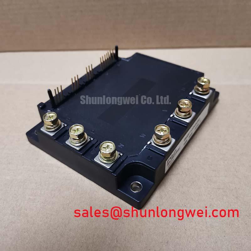
The architecture of the 6MBP100KB060 incorporates six IGBT dies paired with fast-recovery freewheeling diodes alongside integrated high-voltage control ICs. The dedicated gate-driver stage delivers optimized turn-on and turn-off switching transitions, reducing both electromagnetic emissions and switching energy dissipation across operating carrier frequencies. Exploring the integrated IPM structure reveals how matching drive characteristics internally prevents stray inductances from degrading switching margins.
Thermal dissipation represents a pivotal metric in closed power cabinets. The junction-to-case thermal resistance ($R_{th(j-c)}$) of the IGBT section is rated at 0.36 °C/W. To visualize this, consider thermal resistance as the constriction within an exhaust pipe: a smaller resistance value allows heat energy to escape swiftly into the heatsink rather than congesting at the semiconductor die, preventing excessive junction temperatures during cyclic load peaks. Tracking this behavior through proper thermal impedance evaluation ensures long-term operational integrity.
Hardware protection features include short-circuit trip monitoring, overcurrent limiting, overtemperature cutoff, and control power supply monitoring. The embedded under-voltage lockout mechanism actively inhibits switching when the control voltage ($V_{CC}$) dips below safe threshold levels. This prevents the IGBT from operating in the high-dissipation linear active region, shielding the device against localized thermal stress.
Optimized Application Scenarios
- Industrial Variable Frequency Drives (VFDs): Suited for 200V-240V AC three-phase input motor systems up to 15 kW where compact footprint and integrated inverter layout simplify inverter cabinet assembly.
- Servo Axis Amplifiers: The matched gate dynamics deliver clean current waveforms, ensuring predictable torque response across variable motor speeds.
- Industrial Uninterruptible Power Supplies (UPS): Fast-recovery internal freewheeling diodes handle inductive back-EMF without excessive reverse recovery snappy transients.
- Auxiliary Power Inverters: The isolated baseplate simplifies mechanical grounding in commercial equipment and heating, ventilation, and air conditioning (HVAC) compressors.
The 6MBP100KB060 provides exceptional electrical and mechanical density for 200V-class industrial inverter stages requiring comprehensive integrated power semiconductor protection.
Key Electrical and Thermal Specifications
| Parameter | Symbol | Ratings / Conditions | Unit |
|---|---|---|---|
| Absolute Maximum Ratings ($T_c = 25^circtext{C}$ unless noted) | |||
| Collector-Emitter Voltage | $V_{CES}$ | 600 | V |
| Continuous Collector Current | $I_C$ | 100 ($T_c = 25^circtext{C}$) | A |
| Peak Collector Current | $I_{CP}$ | 200 (1 ms) | A |
| Collector Power Dissipation | $P_C$ | 347 (Per IGBT device) | W |
| Isolation Voltage | $V_{isol}$ | 2500 (AC 1 minute) | V |
| Electrical Characteristics ($T_j = 25^circtext{C}$) | |||
| Collector-Emitter Saturation Voltage | $V_{CE(sat)}$ | 2.7 (Typ. at $I_C = 100text{A}$) | V |
| Diode Forward Voltage Drop | $V_F$ | 2.5 (Typ. at $I_F = 100text{A}$) | V |
| Supply Voltage for Control Circuit | $V_{CC}$ | 13.5 to 16.5 (Nominal 15) | V |
| Thermal Characteristics | |||
| IGBT Thermal Resistance (Junction-to-Case) | $R_{th(j-c)}$ | 0.36 (Max) | °C/W |
| Diode Thermal Resistance (Junction-to-Case) | $R_{th(j-c)}$ | 0.70 (Max) | °C/W |
Engineer Inquiries and Design FAQ
What optocoupler bandwidth is recommended for driving the control pins of 6MBP100KB060?
High-speed optocouplers with high Common Mode Transient Immunity (CMTI > 10 kV/μs) and signal propagation delay under 0.8 μs are recommended to ensure clean edge transitions and prevent false triggering during steep $dv/dt$ events.
What is the required tightening torque for mounting the module to a heatsink?
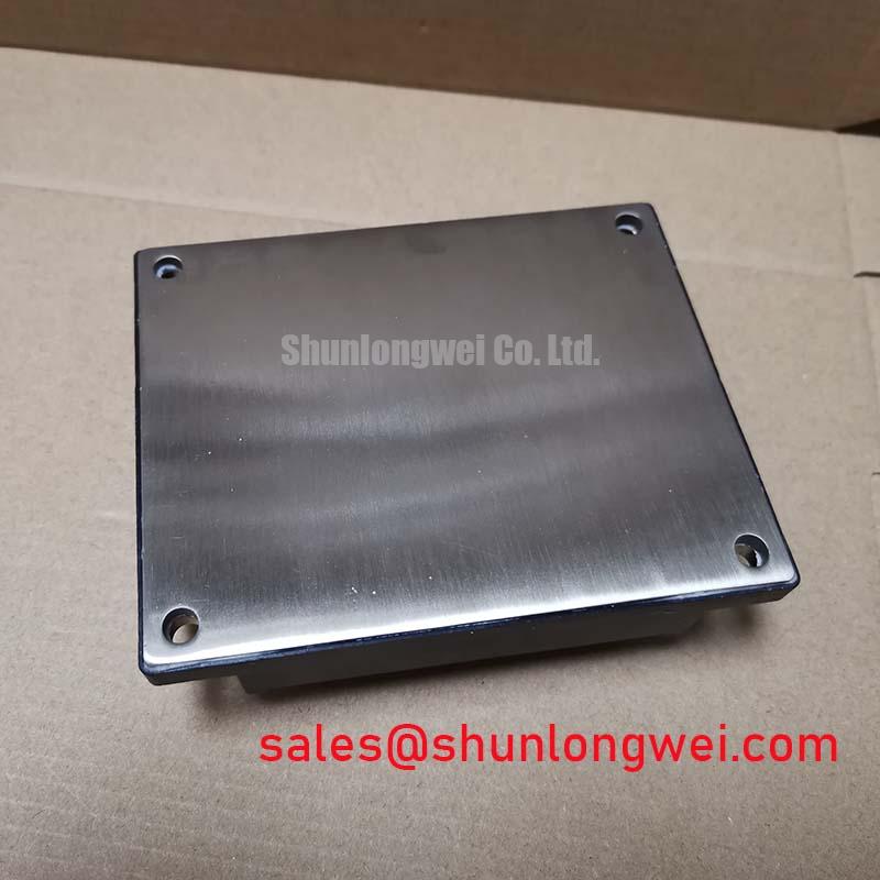
The module requires M5 mounting screws fastened with a specified torque of 2.5 to 3.5 N·m. Applying uniform thermal grease at a thickness of 100 μm is critical to avoid void formation and localized mechanical stress across the copper baseplate.
How does the built-in alarm signal function during fault conditions?
When short-circuit, overcurrent, or control supply under-voltage conditions trip internal sensors, an active-low open-collector alarm output terminal pulls low, allowing host microcontrollers to initiate controlled system shutdown procedures.
Procurement and Technical Implementation Support
Integrating the 6MBP100KB060 enables engineers to streamline inverter hardware designs while maintaining robust electrical protection in demanding industrial motor drives. Designers can review supplementary technical references within the power semiconductor directory to align their layout strategies with verified device ratings.