PM20CVL060-33 Intelligent Power Module: 600V 20A Three-Phase Inverter Technical Overview and Applications
PM20CVL060-33 Intelligent Power Module: 600V 20A Three-Phase Inverter
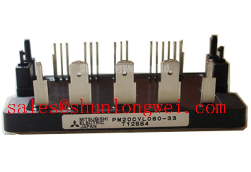
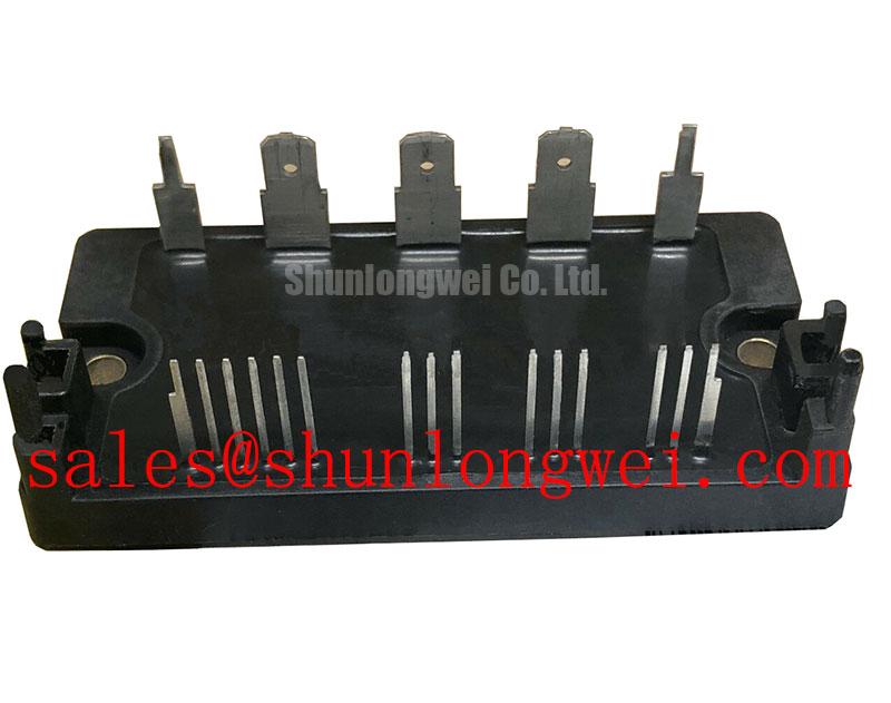
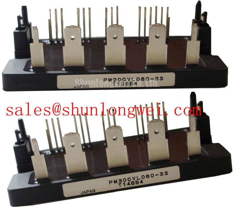
The PM20CVL060-33 is a 600V, 20A three-phase IPM (Intelligent Power Module) designed for low-to-medium power motor drives and power conversion. It combines low-loss IGBT switches with optimized internal gate drive circuitry and comprehensive fault protection. This integrated architecture minimizes parasitic switching transients and reduces board space in high-density converter layouts.
- Core Ratings: 600V collector-emitter voltage, 20A continuous collector current, 40A peak current capability.
- Built-In Protections: Over-current/short-circuit detection, control supply under-voltage lockout, and over-temperature feedback.
- Key Engineering Benefits: Eliminates discrete driver complexity while maintaining 2500 Vrms isolation for enhanced system safety.
Download Official PM20CVL060-33 Technical Documentation (PDF)
Technical Analysis Around the Unique Value Proposition
The distinct value proposition of the PM20CVL060-33 lies in its matched silicon-to-driver integration. By co-packaging the dedicated High-Voltage IC (HVIC) drivers directly adjacent to the power dies, stray loop inductance between the driver stage and the gate is kept negligible. This structure prevents false turn-on events caused by high dv/dt noise, a recurring challenge in discrete power designs.
Thermal management is further streamlined by an electrically isolated ceramic baseplate. You can think of thermal resistance in a power module like the diameter of a drainage pipe: lower thermal impedance allows large surges of thermal energy to drain quickly into the heatsink, keeping internal die temperatures well below safe limits. The thermal impedance junction-to-case (Rth(j-c)) of the PM20CVL060-33 ensures reliable operation during repetitive switching cycles up to 20 kHz.
The module implements integrated short-circuit (SC) and under-voltage lockout (UVLO) monitoring directly at the switch level. When a supply dip or load fault occurs, the internal logic executes a soft shutdown sequence. This suppresses excessive di/dt voltage spikes across the DC bus without requiring external active clamping components. For engineers exploring architectural trade-offs, our technical guide explains the IPM advantage in modern motion controllers.
Optimized Application Scenarios
- Industrial Variable Frequency Drives (VFDs): Provides three-phase bridge output for 0.75 kW to 1.5 kW AC induction and permanent magnet synchronous motors.
- Commercial HVAC Compressors & Fans: Low saturation voltage and integrated thermal sensing enable quiet, efficient pulse-width modulation at switching speeds above audible thresholds.
- Robotic Actuation Systems: Low parasitic capacitance and tight gate timing matching offer rapid dynamic response for precision multi-axis controllers.
- General Power Semiconductors Applications: Serves as a compact power stage for auxiliary power units and servo positioning drives.
Best match: Compact three-phase inverter platforms requiring reliable gate protection, low thermal resistance, and simplified layout within standard 200V–400V AC grid equipment.
Key Electrical & Thermal Specifications
| Parameter | Symbol | Rating / Condition | Unit |
|---|---|---|---|
| Absolute Maximum Ratings (Tj = 25°C unless noted) | |||
| Collector-Emitter Voltage | VCES | 600 | V |
| Continuous Collector Current | IC | 20 (Tc = 100°C) | A |
| Peak Collector Current | ICP | 40 | A |
| Isolation Voltage | Viso | 2500 (60Hz, AC 1 min, base to pins) | Vrms |
| Electrical Characteristics (Inverter Part, Tj = 25°C) | |||
| Collector-Emitter Saturation Voltage | VCE(sat) | 1.8 (Typ) / 2.3 (Max) @ IC = 20A, VD = 15V | V |
| FWD Forward Voltage Drop | VEC | 2.2 (Typ) @ -IC = 20A | V |
| Switching Turn-Off Time | toff | 1.7 (Typ) @ VCC = 300V, IC = 20A | µs |
| Thermal & Mechanical Characteristics | |||
| Operating Junction Temperature | Tj | -20 to +150 | °C |
| Mounting Torque | M | 1.47 – 1.96 (M4 screw) | N·m |
Engineer FAQ
What is the recommended control supply voltage (VD) for PM20CVL060-33?
The nominal control supply voltage is 15V DC (operating window 13.5V to 16.5V). Applying voltage below 12.5V trips the built-in under-voltage protection, preventing incomplete gate turn-on and high-conduction dissipation.
How do you suppress high-frequency switching noise on the logic inputs?
Keep the control signal traces as short as possible and route them away from high-current AC output pins. Utilizing high-speed optocouplers with high common-mode transient immunity (CMTI) ensures clean control signals. For deeper layout practices, reference our overview of robust gate drive design.
What mounting procedure prevents mechanical stress on the ceramic substrate?
Use M4 mounting screws torqued evenly in two passes to a final range of 1.47 to 1.96 N·m. Ensure the heatsink contact surface flatness is within 50 µm and apply a uniform 100 µm layer of high-performance thermal grease to avoid localized hotspots.
Reliable Power Integration for Demanding Control Systems
The PM20CVL060-33 delivers a balance of rugged protection, low switching loss, and compact mechanical packaging. By consolidating driver stages and protective logic directly beside 600V 20A IGBT switches, the module helps power engineers simplify hardware layouts while maintaining high operational reliability across industrial motion control platforms.