Analyzing the Fuji 1D500A-030A: A 500A High-Gain Darlington Module
“`html
Fuji Electric 1D500A-030A Power Transistor Module | 300V 500A
Introduction and Core Highlights
The Fuji Electric 1D500A-030A is a high-current power transistor module that integrates six Darlington transistors with free-wheeling diodes. Its design is centered on providing a high DC current gain (hFE) and an electrically isolated mounting base, a combination that simplifies both the drive circuit and the thermal management system for high-power industrial equipment.
- Core Specifications: 300V VCEO | 500A IC | hFE of 150 (Typical)
- Key Advantages: Reduces base drive power requirements due to high gain. Simplifies and improves heatsink mounting with a 2500V isolated base.
- Design Consideration: The high hFE means a lower base current is needed to achieve full 500A collector current, reducing stress and power loss in the control stage.
Download Official Datasheet (PDF)
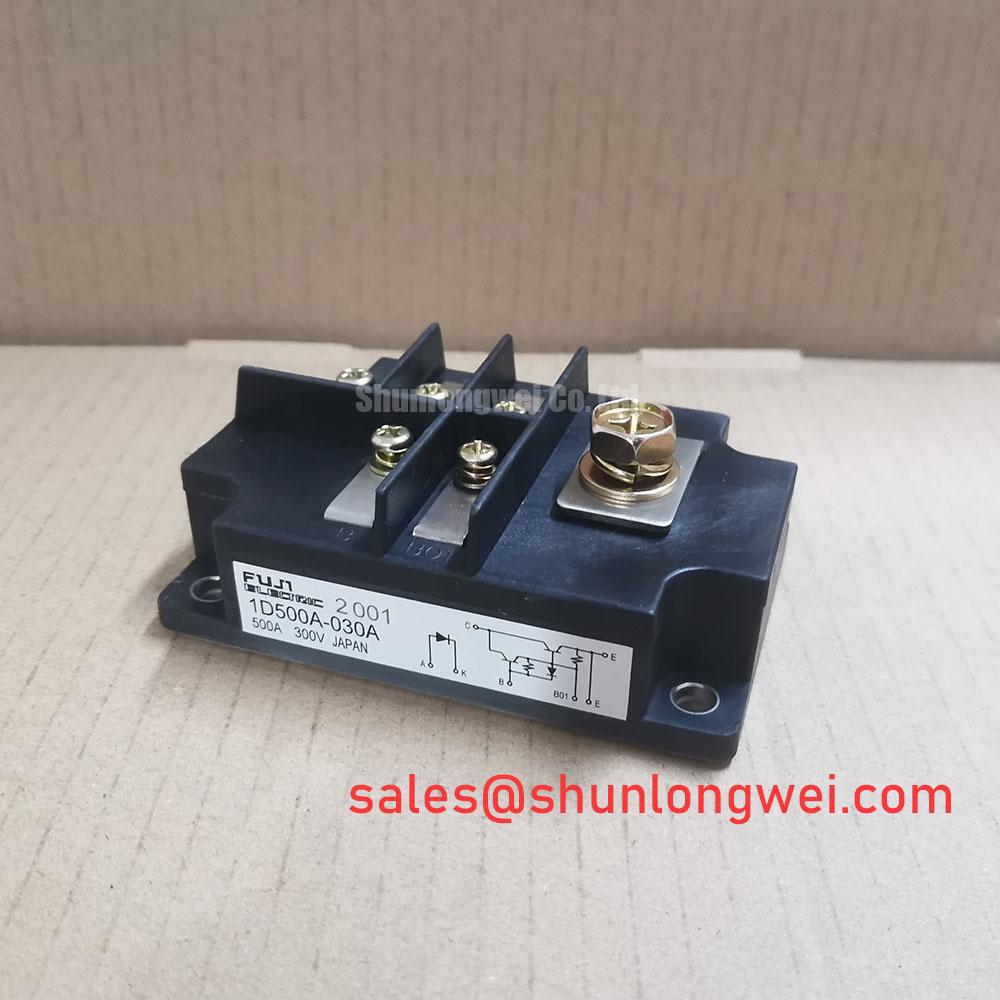
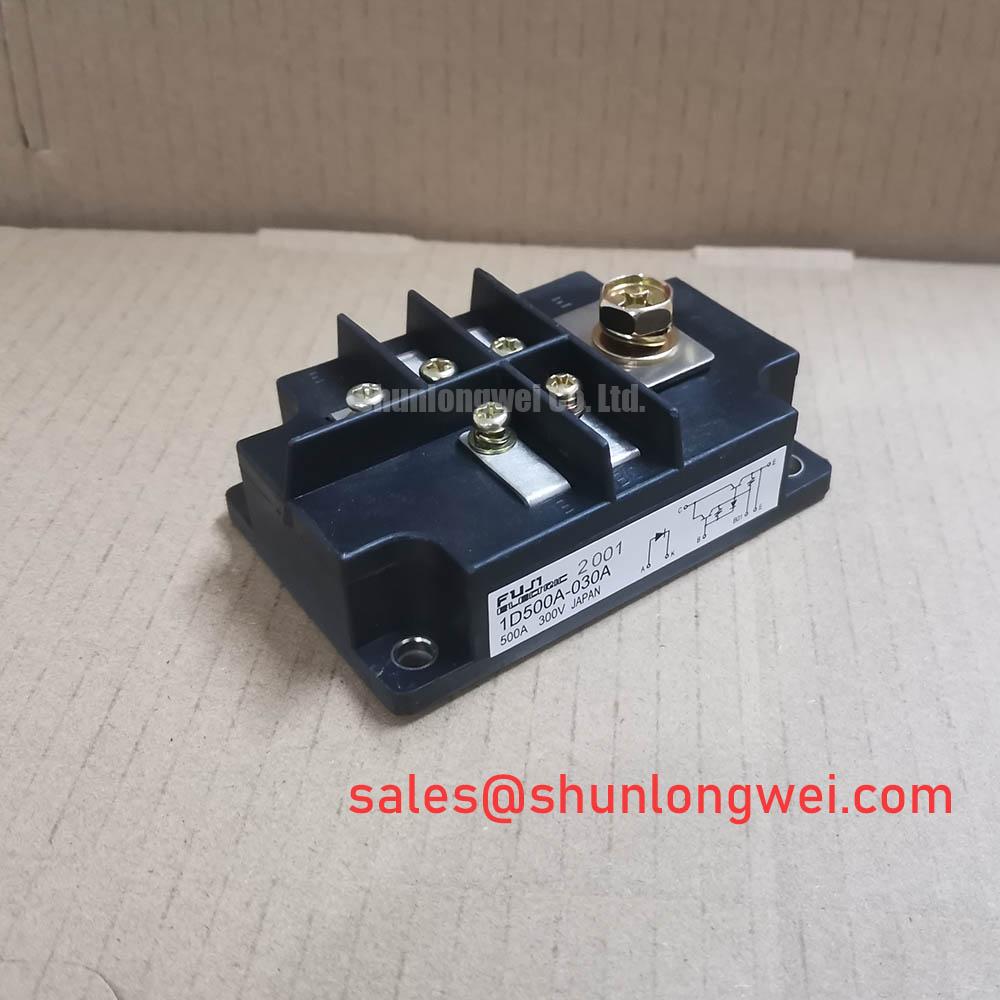
Technical Analysis Based on Core Features
A defining characteristic of the 1D500A-030A module is its high DC current gain (hFE), with a typical value of 150 at a collector current of 500A. This high gain is critical for system efficiency. Think of hFE as leverage for electrical current; a high value means a small input current at the base can control a significantly larger current flow through the collector. For an engineer, this translates to a less complex and lower-power base drive circuit, which in turn reduces overall system power loss and component count. For more context on the trade-offs involved in semiconductor performance, see our guide on balancing IGBT density and robustness.
The module features an electrically isolated base, rated for 2500V AC for one minute. This integral isolation addresses a common challenge in power system assembly. It allows the module to be mounted directly onto a heatsink without requiring a separate, external insulating layer, such as a mica or silicone pad. The primary engineering benefit is a simplified assembly process and a more effective thermal interface. By removing an extra layer, the thermal resistance from the device junction to the heatsink is reduced, leading to more efficient heat dissipation and improved long-term reliability. This principle is fundamental to the foundation of high-voltage reliability.
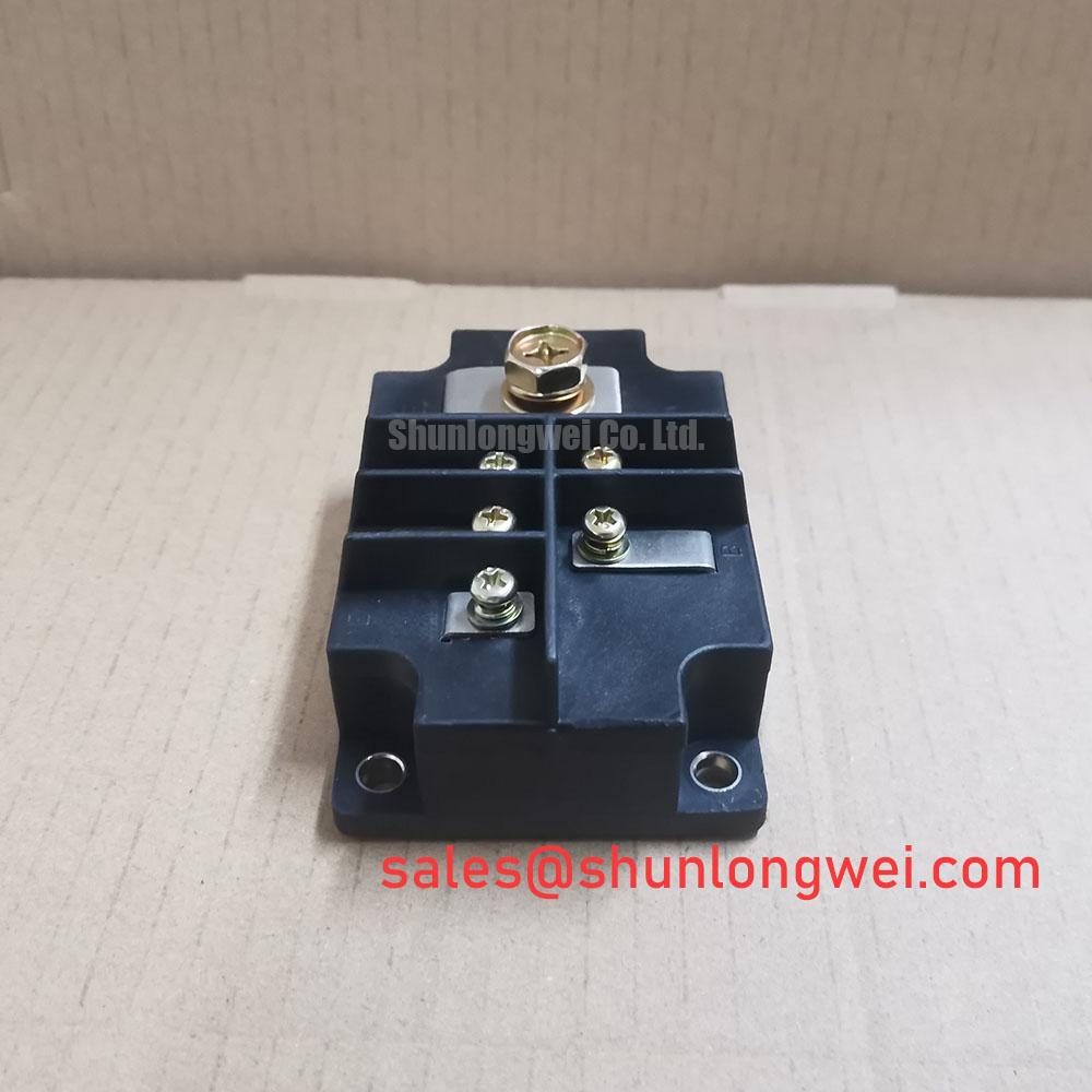
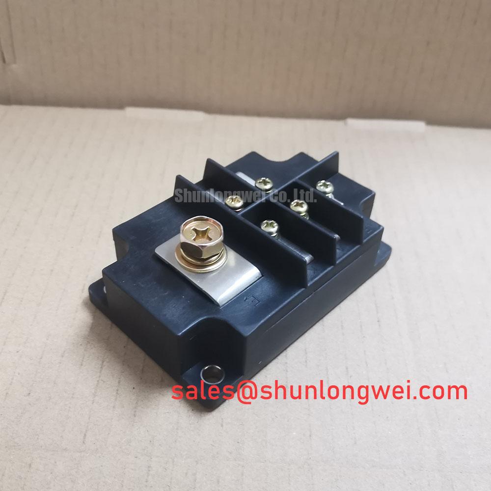
Optimized Application Scenarios
The specifications of the 1D500A-030A make it a strong candidate for several high-power applications:
- High-Power DC Motor Drives: The 500A current rating is well-suited for controlling large industrial DC motors, while the integrated free-wheeling diodes safely manage inductive kickback.
- Industrial Inverters: Its robust current handling is ideal for the output stage of low-frequency, high-power inverters used in manufacturing and process control.
- Switching Regulators: Provides the necessary high-current switching capability for large-scale power supplies and DC-DC converters.
- Welding Power Supplies: The module’s ability to handle high power dissipation (1780W) makes it suitable for managing the demanding current profiles in welding equipment.
This module is best matched for applications requiring robust, high-current control where simplified driver and thermal designs are priorities.
Key Specification Parameters
| Absolute Maximum Ratings | |
|---|---|
| Collector-Emitter Voltage (VCEO) | 300 V |
| Collector-Base Voltage (VCBO) | 300 V |
| Emitter-Base Voltage (VEBO) | 7 V |
| Collector Current (DC) (IC) | 500 A |
| Base Current (DC) (IB) | 20 A |
| Collector Power Dissipation (PC) | 1780 W |
| Operating Junction Temperature (Tj) | +150 °C |
| Electrical Characteristics | |
| Collector Cut-off Current (ICES) | 10 mA (max) at VCE=300V |
| Collector-Emitter Saturation Voltage (VCE(sat)) | 2.0 V (max) at IC=500A, IB=10A |
| DC Current Gain (hFE) | 75 (min) at IC=500A, VCE=2V |
| Diode Forward Voltage (VF) | 2.5 V (max) at IF=500A |
| Thermal and Isolation Characteristics | |
| Thermal Resistance (Rth(j-c), Transistor) | 0.07 °C/W (max) |
| Thermal Resistance (Rth(j-c), Diode) | 0.14 °C/W (max) |
| Isolation Voltage (Visol) | 2500 V (AC, 1 minute) |
Engineer’s FAQ
1. What is the typical base current required to drive the 1D500A-030A at its rated collector current?
Based on the datasheet, the typical hFE is 150 at an IC of 500A. A simplified calculation (IB = IC / hFE) suggests a base current of approximately 3.33A. The datasheet specifies a maximum VCE(sat) of 2.0V with an IB of 10A, providing a reference point for robust drive design.
2. Do I need a separate thermal insulation pad when mounting this module?
No. The 1D500A-030A features an isolated base rated for 2500V. This allows direct mounting to a heatsink. For optimal thermal performance, it is important to ensure the mounting surface is flat and to apply a thin, uniform layer of thermal grease.
3. What is the function of the built-in free-wheeling diode?
The integrated free-wheeling diode provides a path for current to flow when the transistor switches off in an inductive load circuit, such as a motor winding. This protects the transistor from potentially damaging voltage spikes caused by the collapsing magnetic field. Understanding this component is key, much like knowing why soft recovery diodes are critical for IGBTs.
Design Enablement
The 1D500A-030A power transistor module offers a robust component for high-current control systems. Its high current gain and integral electrical isolation directly address key engineering challenges, enabling the development of power stages with more efficient driver circuits and simplified, reliable thermal management schemes.
“`