BSM20GP C60 IGBT Module: A Technical Analysis
BSM20GP C60 IGBT Module: A Technical Analysis
Introduction to the BSM20GP C60
The BSM20GP C60 is an IGBT (Insulated Gate Bipolar Transistor) power module designed for high-efficiency power conversion applications. It integrates multiple IGBTs and freewheeling diodes into a single, compact package, simplifying the design and assembly of three-phase inverters, motor drives, and uninterruptible power supplies (UPS). This module is engineered to provide a balance of low conduction and switching losses, contributing to improved thermal performance and system reliability.
The device’s architecture facilitates reduced stray inductance compared to discrete component solutions, which is a critical factor in mitigating voltage overshoots and enhancing electromagnetic compatibility (EMC). By consolidating the power stage, the BSM20GP C60 enables a more compact mechanical layout and simplifies the thermal management system, making it a practical choice for space-constrained industrial applications.
Key Features and Electrical Characteristics
The BSM20GP C60 is characterized by its 600V collector-emitter voltage (VCES) and a nominal collector current (IC) rating of 20A. These ratings make it suitable for a wide range of low- to medium-power applications. One of the key performance metrics is its low collector-emitter saturation voltage (VCE(sat)), which is specified under typical operating conditions in the manufacturer’s datasheet. A lower VCE(sat) translates directly to reduced conduction losses, which is the primary source of heat generation when the device is in its on-state.
The module also incorporates fast and soft-recovery freewheeling diodes that are co-packaged with the IGBTs. The characteristics of these diodes are optimized to reduce turn-on losses in the IGBT and to minimize reverse recovery effects, which can be a significant source of electromagnetic interference (EMI). The integrated NTC (Negative Temperature Coefficient) thermistor provides a means for real-time temperature monitoring, allowing for the implementation of over-temperature protection schemes and enhancing the long-term reliability of the power system.
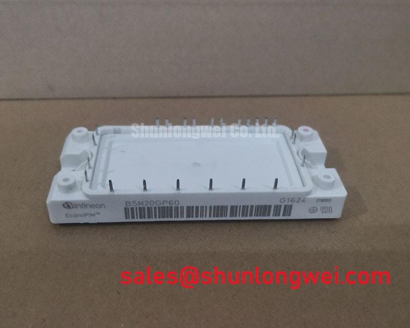

Applications and Use Cases
The BSM20GP C60 is primarily intended for use in three-phase power conversion systems. Its integrated six-pack configuration, which consists of six IGBTs and six diodes, is an ideal fit for standard B6 inverter topologies. Common applications include:
- AC Motor Drives: The module can be used to control the speed and torque of AC induction motors and permanent magnet synchronous motors in industrial automation, HVAC, and appliance applications.
- Uninterruptible Power Supplies (UPS): In online UPS systems, the BSM20GP C60 can be employed in the inverter stage to convert DC power from batteries into clean and stable AC power.
- Solar Inverters: For grid-tied or off-grid solar applications, this module can serve as the core of the DC-AC inverter, converting the DC output of solar panels into AC power.
- Welding Power Supplies: The module’s switching characteristics and current handling capabilities make it suitable for inverter-based welding machines.
The selection of the BSM20GP C60 for a particular application should be based on a thorough analysis of the system’s power requirements, switching frequency, and thermal constraints, with careful reference to the official datasheet for detailed performance curves and operating limits.
Thermal Management and Mounting
Effective thermal management is crucial for ensuring the reliability and performance of any power module. The BSM20GP C60 is designed to be mounted on a heatsink to dissipate the heat generated during operation. The datasheet provides the thermal resistance from junction to case (RthJC), which is a key parameter for heatsink selection and thermal design. To achieve a low thermal resistance between the module’s baseplate and the heatsink, it is essential to use a thermal interface material (TIM), such as thermal grease or a phase-change material, and to apply the correct mounting torque to the screws as specified by the manufacturer.
The integrated NTC thermistor can be connected to a control circuit to monitor the module’s temperature. This allows the system to reduce power or shut down gracefully if the temperature exceeds safe operating limits, thereby preventing catastrophic failure. A well-designed thermal system not only ensures reliability but also allows the module to be operated closer to its maximum rated performance.
Gate Drive and Control Considerations
Proper gate drive design is essential for achieving the desired switching performance from the BSM20GP C60. The gate driver circuit must be capable of supplying the required gate charge (QG) to turn the IGBTs on and off efficiently. The gate-emitter voltage (VGE) should be regulated within the limits specified in the datasheet, typically with a positive voltage (e.g., +15V) for turn-on and a zero or negative voltage (e.g., 0V or -5V) for turn-off. The use of a negative gate voltage can help to prevent spurious turn-on due to the Miller effect, especially in high dv/dt environments.
The layout of the gate drive circuit should be carefully considered to minimize inductance in the gate loop, as this can cause ringing and affect switching behavior. It is also important to consider protection features such as short-circuit protection (desaturation detection) and under-voltage lockout (UVLO) in the gate driver design to protect the IGBT module from fault conditions. For a comprehensive understanding of these design considerations, engineers should consult the relevant application notes and technical literature provided by the manufacturer.
For detailed specifications, performance curves, and application guidelines, please refer to the official BSM20GP C60 datasheet provided by the manufacturer.
Download Official Datasheet (PDF)
Technical Specifications
| Parameter | Value |
|---|---|
| Collector-Emitter Voltage (VCES) | 600 V |
| Continuous Collector Current (IC) @ TC = 80°C | 20 A |
| Total Power Dissipation (Ptot) @ TC = 25°C | 130 W |
| Gate-Emitter Voltage (VGES) | ±20 V |
| Collector-Emitter Saturation Voltage (VCE(sat)) @ IC = 20A, VGE = 15V | 1.95 V (Typ) |
| Configuration | Six-Pack |
| Isolation Voltage (VISOL) | 2500 V (RMS, f=50Hz, t=1min) |
Frequently Asked Questions (FAQ)
What is the primary advantage of using an integrated module like the BSM20GP C60 over discrete IGBTs?
The main advantage is system integration. The BSM20GP C60 combines six IGBTs and six freewheeling diodes in a single, thermally optimized package. This reduces the component count, simplifies the PCB layout, minimizes stray inductance, and streamlines the assembly process. The result is a more compact, reliable, and often more cost-effective solution for three-phase inverter designs compared to using twelve separate discrete components.
How should the NTC thermistor be used for temperature monitoring?
The integrated NTC thermistor provides a resistance value that changes predictably with the module’s temperature. This thermistor should be connected to a voltage divider or a dedicated analog input on a microcontroller. By measuring the voltage and using the resistance-temperature characteristic curve provided in the datasheet, the control system can accurately determine the module’s operating temperature. This data can be used to implement thermal protection, such as derating the output current or shutting down the system if a preset temperature limit is exceeded.
What are the critical considerations for mounting the BSM20GP C60 to a heatsink?
To ensure optimal thermal performance, several factors are critical. First, the heatsink surface must be clean, flat, and free of burrs. Second, a high-quality thermal interface material (TIM) must be applied evenly between the module’s baseplate and the heatsink to fill any microscopic air gaps. Finally, the module must be secured using the correct screw size and mounting torque as specified in the datasheet. Uneven or incorrect torque can lead to poor thermal contact and mechanical stress on the module.