SM16Z4689: An Integrated 4-Line TVS Array for Robust ESD Protection
SM16Z4689 TVS Diode Array for I/O Port ESD Protection
Integrated 4-Line Transient and ESD Protection
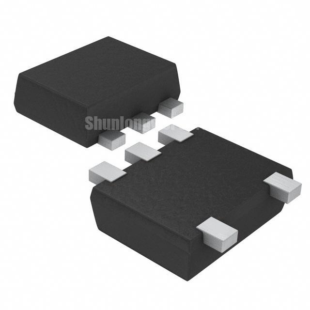
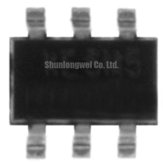
The SM16Z4689 is a transient voltage suppressor (TVS) array structured to provide robust protection for four I/O or data lines from damage due to electrostatic discharge (ESD) and other transient events. This device integrates four protection channels into a single compact SOT-23-6L package, offering a space-saving alternative to using multiple discrete components for circuit protection.
- Core Specifications: 16V VRWM | 4-Line Protection | SOT-23-6L Package
- Key Advantages: Reduces component count and required PCB area, suitable for control lines operating above standard logic levels.
Its 16V reverse standoff voltage makes it a practical choice for interfaces where operating voltages exceed the typical 5V rails, providing a higher margin for system signals. For technical specifications, you can reference compiled data from trusted sources.
Access Technical Specifications
Technical Analysis of the SM16Z4689
The primary engineering value of the SM16Z4689 lies in its consolidation of protection. By integrating four TVS diodes into one package, it directly addresses the need for higher layout density in modern electronics. This approach replaces four individual components, reducing the bill of materials (BOM), simplifying the assembly process, and minimizing the overall footprint. Such integration also ensures that the protective characteristics across all four channels are closely matched, leading to more predictable performance in multi-line bus applications like power semiconductors interfaces.
A critical parameter for this device is its 16V reverse standoff voltage (VRWM). This specification defines the maximum continuous voltage that can be applied without the device drawing significant current. You can visualize this as the operational ceiling for the protected circuit. The 16V rating provides ample headroom for 12V systems, common in industrial controls, ensuring the SM16Z4689 remains electrically transparent during normal operation. It only activates when a transient voltage exceeds its breakdown voltage, safely diverting harmful energy away from sensitive downstream components. This is a key factor in ensuring system reliability without interfering with signal integrity.
Optimized Application Scenarios
The characteristics of the SM16Z4689 make it a strong candidate for several applications:
- Industrial Control Lines: The 16V VRWM is well-suited to protect I/O modules and sensor interfaces in systems that utilize a 12V bus.
- General Purpose I/O (GPIO) Banks: It offers a single-chip solution for protecting multiple microcontroller GPIO pins exposed to external connections and potential ESD strikes.
- Communication Buses (I2C, SPI): Provides consolidated protection for the multiple lines (SDA, SCL, MISO, MOSI) used in these common peripheral interfaces where operating speeds are moderate.
- User Interface Hardware: Effectively shields button matrices, keypads, and other human-interface connections that are susceptible to ESD from user interaction.
This device is an optimal fit for applications needing consolidated ESD immunity for multiple I/O or control lines operating up to 16V.
Key Specifications of the SM16Z4689
| Electrical Characteristics (TA = 25°C unless otherwise noted) | |
|---|---|
| Parameter | Value |
| Reverse Standoff Voltage (VRWM) | 16 V |
| Breakdown Voltage (VBR) @ 1mA | 17.8 V (Min) / 21.8 V (Max) |
| Reverse Leakage Current (IR) @ VRWM | 1 µA (Max) |
| Junction Capacitance (CJ) (I/O to GND) | 30 pF (Typ) |
| Package | SOT-23-6L |
Engineer’s Frequently Asked Questions
- 1. What is the breakdown voltage range for the SM16Z4689?
- The reverse breakdown voltage (VBR) is specified to be between 17.8V and 21.8V when measured at a test current of 1mA. Within this range, the device transitions into its protective avalanche mode to clamp transient overvoltages.
- 2. How does the SOT-23-6L package assist with PCB layout?
- The SOT-23-6L is a small-outline package that occupies minimal board space. Its pin configuration is often designed for “flow-through” routing, where input and output traces for a given line are on opposite sides of the package. This simplifies PCB layout and helps minimize parasitic inductance, which is crucial for maintaining signal quality.
- 3. Is this TVS array suitable for high-speed signals like USB 3.0 or HDMI?
- With a typical junction capacitance of 30pF, the SM16Z4689 is not recommended for high-speed differential pairs found in interfaces like HDMI or USB 3.0. This level of capacitance can degrade the signal integrity. It is better suited for lower-frequency applications such as GPIO, push-buttons, and industrial control buses.
- 4. What is the pin configuration for the common ground connection?
- This device uses a common anode configuration. Based on typical SOT-23-6L TVS array layouts, pins 2 and 5 are internally connected and should be tied directly to the system’s ground plane for the most effective protection path.
Enabling Robust Interface Protection
For engineering teams tasked with protecting multiple I/O lines in a compact and cost-effective manner, the SM16Z4689 provides a practical solution. Its integration of four protection channels and a 16V operational ceiling allows for the development of resilient systems by safeguarding vulnerable interfaces from common electrical threats. This approach supports streamlined design and manufacturing without compromising on essential circuit protection.