CM150MXUD-24T IGBT Module: A Technical Review for Industrial Applications
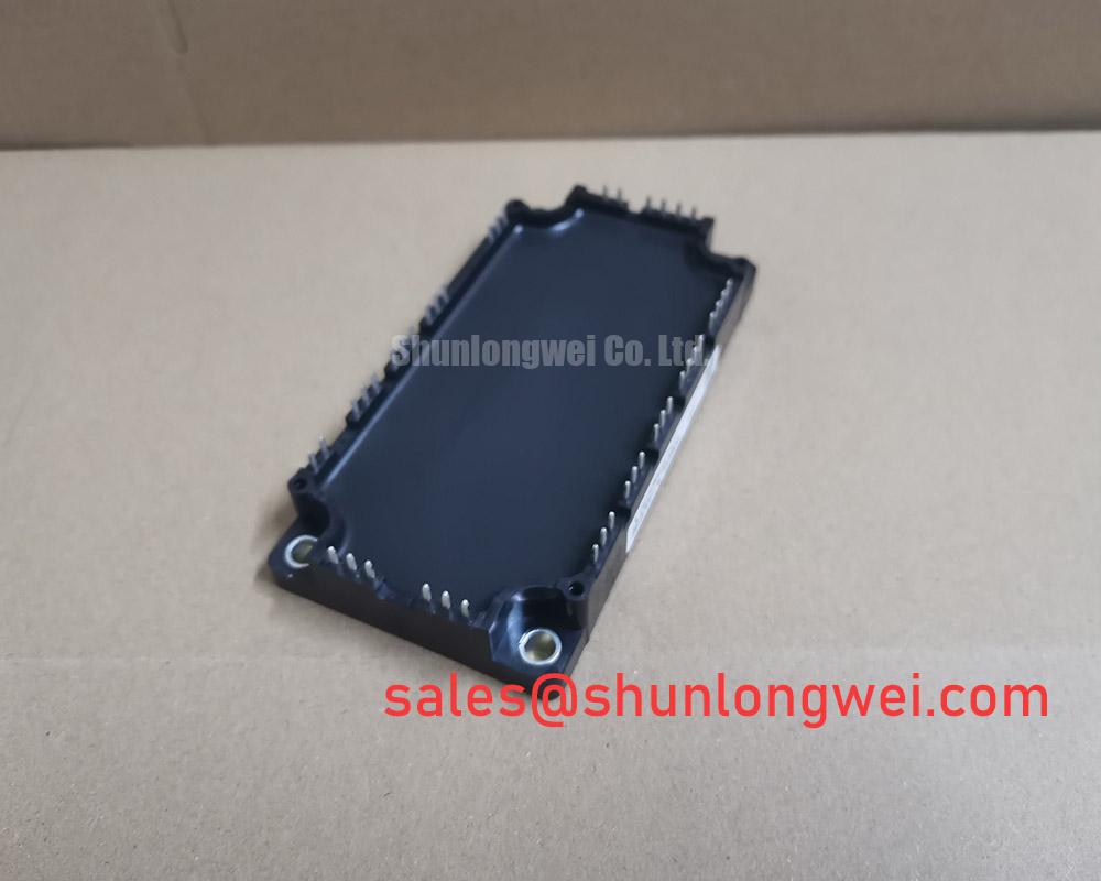
CM150MXUD-24T Mitsubishi 1200V 150A IGBT Module
Introduction and Core Highlights
The Mitsubishi CM150MXUD-24T is a CIB (Converter + Inverter + Brake) IGBT module engineered for high-power switching applications. It delivers a robust performance profile centered on a balanced trade-off between conduction and switching losses, coupled with an integrated NTC thermistor for real-time thermal monitoring. This combination provides a reliable foundation for developing efficient and durable power conversion systems.
- Core Specifications: 1200V | 150A (Inverter) | VCE(sat) 2.2V (typ)
- Key Advantages: Facilitates simplified thermal protection design, offers dependable performance for industrial motor control.
- User Intent Answered: An integrated NTC thermistor allows for direct temperature measurement, enabling precise over-temperature protection and enhancing long-term system reliability.
Download the Official CM150MXUD-24T Datasheet (PDF)

Technical Analysis for System Design
The engineering value of the CM150MXUD-24T lies in its balanced characteristics, which are documented in its datasheet. The typical collector-emitter saturation voltage (VCE(sat)) is specified at 2.2V at the nominal current of 150A (Tj=125°C). This parameter is a primary determinant of conduction losses, directly impacting the module’s thermal load during operation. A controlled VCE(sat) ensures that heat generation is manageable, which is a critical factor in achieving high system efficiency and reliability. The module’s performance is further supported by a robust freewheeling diode (FWD) co-packaged with the IGBT, ensuring efficient handling of inductive currents during switching events.
A significant feature for system protection and longevity is the integrated NTC (Negative Temperature Coefficient) thermistor. This component provides a direct and reliable method for monitoring the module’s internal temperature. By tracking the thermistor’s resistance, control systems can implement precise over-temperature shutdown or derating protocols. This prevents the IGBT from exceeding its maximum junction temperature of 175°C, a condition that could otherwise lead to accelerated aging or catastrophic failure. For a deeper understanding of thermal management, explore our guide on the practical use of the Zth curve.
Effective thermal dissipation is governed by the module’s thermal resistance. The datasheet specifies the junction-to-case thermal resistance (Rth(j-c)) for the IGBT as 0.165 K/W. This value can be thought of like the width of a pipe for heat flow; a lower value indicates a wider pipe, allowing heat to escape more easily from the active semiconductor chip to the heatsink. Proper management of this thermal path is essential for maximizing the performance and operational lifespan of the power semiconductor device.
Optimized Application Scenarios
The specifications of the CM150MXUD-24T make it a strong candidate for a range of demanding industrial applications:
- AC Motor Controllers: The 1200V blocking voltage provides a sufficient safety margin for 380/400V AC line-operated inverters, while the 150A current rating is suitable for controlling medium-power induction motors.
- General Purpose Inverters: Its balanced switching and conduction performance is well-suited for the variable load conditions typical in general-purpose inverter systems.
- Uninterruptible Power Supplies (UPS): The module’s robust current handling and integrated thermal protection contribute to the high reliability required in critical backup power systems.
- Servo Drives: Fast and controlled switching is necessary for the precise motion control demanded by servo applications, a task this module is equipped to handle.
This module is best matched for industrial power conversion systems where reliable operation and integrated thermal feedback are primary design requirements.
Key Specifications of the CM150MXUD-24T
| Absolute Maximum Ratings (Tj=25°C unless otherwise specified) | |||
|---|---|---|---|
| Parameter | Symbol | Value | |
| Collector-Emitter Voltage | VCES | 1200 V | |
| Gate-Emitter Voltage | VGES | ±20 V | |
| Collector Current (DC, Inverter) | IC | 150 A (Tc=112°C) | |
| Isolation Voltage | Visol | 2500 Vrms (AC, 1 min) | |
| Electrical & Thermal Characteristics (Tj=25°C) | |||
| Parameter | Symbol | Condition | Typ. / Max. Value |
| Collector-Emitter Saturation Voltage | VCE(sat) | IC=150A, VGE=15V, Tj=125°C | 2.10 V / – |
| Thermal Resistance (IGBT, Junction to Case) | Rth(j-c)Q | – | – / 0.165 K/W |
| NTC Thermistor Resistance | R25 | – | 5.0 kΩ |
Engineer’s FAQ
How does the integrated NTC thermistor in the CM150MXUD-24T enhance system reliability?
The NTC thermistor provides a means to measure the module’s approximate base plate temperature close to the semiconductor chips. This data allows the system’s controller to actively monitor thermal conditions. It can trigger alarms, reduce output power (derating), or initiate a complete shutdown if temperatures exceed safe limits, preventing thermal runaway and protecting the IGBT from permanent damage. The importance of this feature is detailed in our article on the role of integrated NTCs in IGBT safety.
What are the recommended mounting torque specifications for the CM150MXUD-24T?
According to the datasheet, the recommended mounting torque for the main terminal screws (M5) is 2.5 to 3.5 N·m. For mounting the module to a heatsink using the mounting screws (M6), the recommended torque is 3.0 to 4.0 N·m. Applying the correct torque is critical for ensuring both a reliable electrical connection and optimal thermal transfer to the heatsink.
What is the purpose of the freewheeling diode (FWD) in this IGBT module?
The FWD is essential in circuits driving inductive loads, such as electric motors. When the IGBT turns off, the energy stored in the motor’s inductance must have a path to flow; otherwise, it would create a damagingly high voltage spike across the IGBT. The FWD provides this path, allowing the current to “freewheel” safely until it dissipates or the IGBT turns on again. The characteristics of this diode are critical to system performance, a topic covered in our analysis of soft recovery diodes.
How is the brake chopper circuit used?
The integrated brake chopper is used to manage regenerative energy. When a motor decelerates, it acts as a generator, sending energy back to the DC bus and increasing its voltage. The brake chopper connects an external power resistor across the DC bus when the voltage exceeds a set limit. This dissipates the excess energy as heat, protecting the inverter from overvoltage damage.
Enabling Robust Power System Design
The Mitsubishi CM150MXUD-24T provides a highly integrated and technically sound solution for power conversion. By combining a three-phase inverter, converter, and brake chopper with an essential NTC thermistor in a single package, it allows engineers to design more compact, reliable, and thermally manageable systems. Its specifications are well-aligned with the demands of modern industrial motor drives and power supplies.