Infineon FF150R12RT4: Technical Analysis of an Integrated Rectifier and Chopper Module
Infineon FF150R12RT4 1200V 150A IGBT Module with Chopper
Introduction and Core Highlights
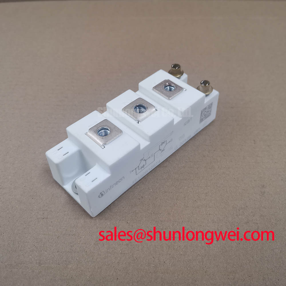
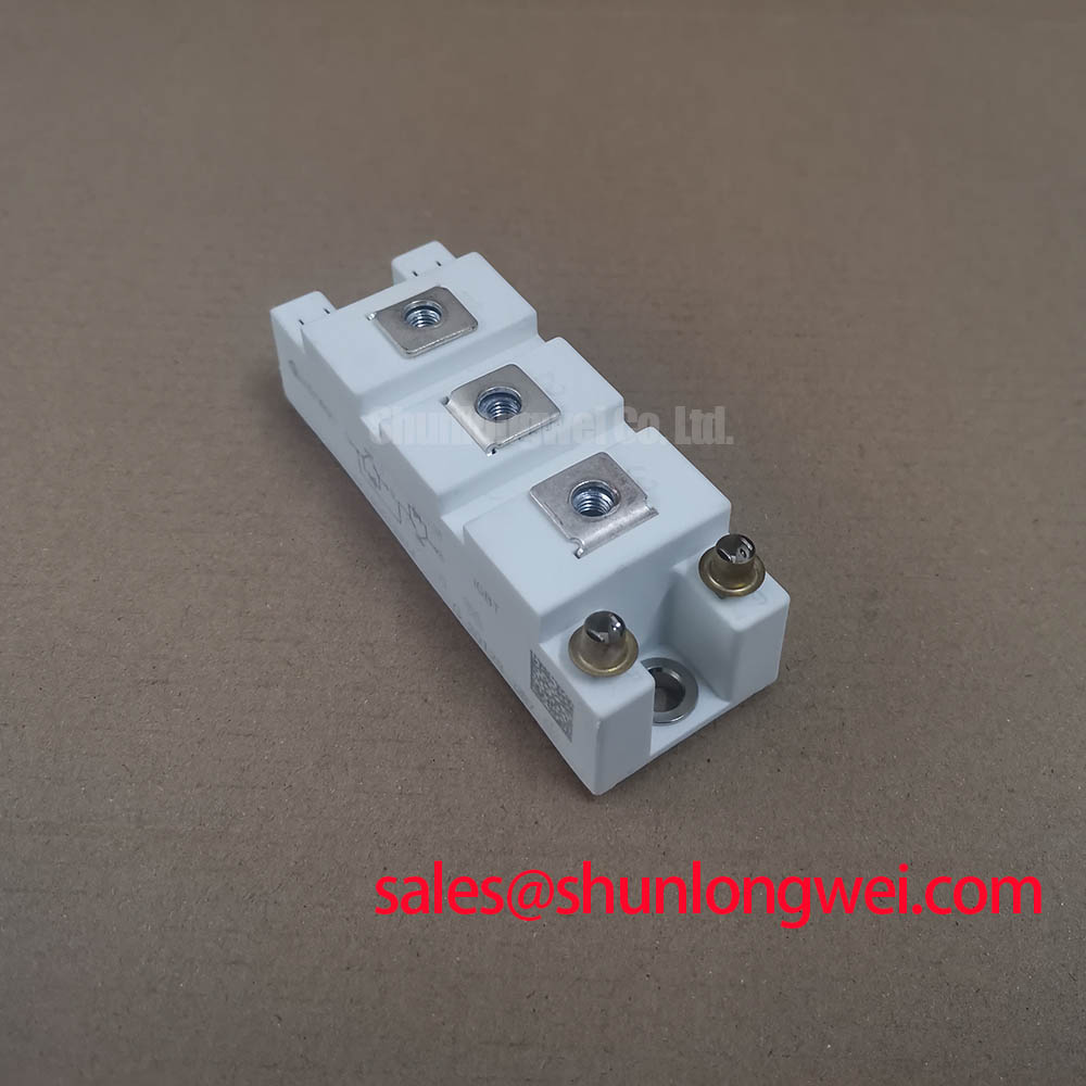
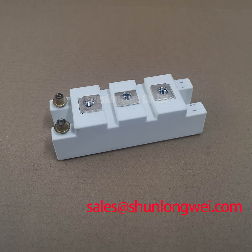
The Infineon FF150R12RT4 is an IGBT module that integrates a full input rectifier bridge and a brake chopper into a single, compact package. This design streamlines the power stage of AC motor drives by combining key functionalities, which significantly reduces system complexity and component count. It leverages Trench/Fieldstop IGBT4 technology to achieve a balance between conduction and switching losses, enhancing overall system efficiency. This integrated approach is particularly beneficial for engineers looking to simplify the design and assembly of variable frequency drives while managing regenerative energy.
- Core Specifications: 1200V | 150A | VCE(sat) 1.70V (typ)
- Key Advantages: Reduces external component count, simplifies thermal management with a common heatsink.
Download Official Datasheet (PDF)
Technical Analysis of Integrated Design
The primary value of the FF150R12RT4 lies in its high level of integration. By incorporating a three-phase input rectifier and a brake chopper IGBT with an anti-parallel freewheeling diode, this module replaces multiple discrete components. This consolidation reduces the overall footprint of the power assembly and minimizes parasitic inductance in the connections between the rectifier, DC link, and chopper. Lower parasitic inductance is critical for reducing voltage overshoots during high-speed switching events, which contributes to improved system reliability and potentially lower EMI. For design teams, this means a simplified bill of materials, a more straightforward PCB layout, and faster assembly times.
A key performance metric is the chopper IGBT’s low collector-emitter saturation voltage (VCE(sat)), with a typical value of 1.70V at its nominal current of 150A (Tvj = 25°C). This parameter is a direct indicator of conduction losses. Think of VCE(sat) as the electrical friction a switch generates when it’s on; a lower value means less energy is converted into waste heat. This efficiency allows for the use of smaller, more cost-effective heatsinks and reduces the overall cooling requirements of the system, which is a critical consideration in power-dense industrial enclosures. More information can be found in our guide to mastering IGBT thermal design.
Optimized Application Scenarios
The features of the FF150R12RT4 make it well-suited for several specific power conversion applications:
- AC Motor Drives (VFDs): The module provides a complete front-end solution. The rectifier converts the mains AC input to the DC bus, while the brake chopper efficiently dissipates regenerative energy from the motor during deceleration.
- Servo Drives: In applications requiring precise motion control and rapid braking, the integrated chopper provides a robust mechanism for managing the energy returned from the motor, ensuring stable DC bus voltage.
- Uninterruptible Power Supplies (UPS): The rectifier stage is ideal for the AC-to-DC conversion needed to charge the battery bank, while the chopper can be part of the power management circuitry.
- Industrial Automation Systems: Any system with motors that undergo frequent start-stop cycles can benefit from the integrated braking capability to protect the DC link capacitors from overvoltage.
This module is best matched for motor drive applications that require a non-regenerative front-end with dynamic braking capabilities for high-inertia loads.
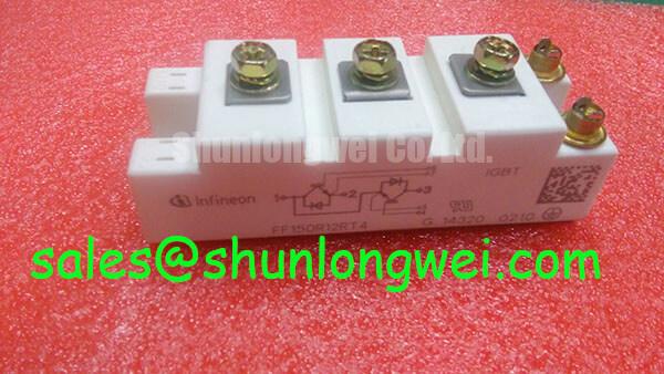
Key Specification Parameters for the FF150R12RT4
| Parameter | Value | ||
|---|---|---|---|
| IGBT Chopper / Inverter (Tvj = 25°C unless otherwise specified) | |||
| Collector-Emitter Voltage (VCES) | 1200 V | ||
| Continuous DC Collector Current (IC nom) | 150 A | ||
| Repetitive Peak Collector Current (ICRM) | 300 A | ||
| Collector-Emitter Saturation Voltage (VCE(sat)) at IC=150A, VGE=15V | 1.70 V (typ.) | ||
| Gate-Emitter Threshold Voltage (VGE(th)) | 5.0 V – 6.5 V | ||
| Rectifier Diode | |||
| Repetitive Peak Reverse Voltage (VRRM) | 1600 V | ||
| DC Forward Current (IF) per Diode | 160 A | ||
| Forward Voltage (VF) at IF=150A | 1.15 V (typ.) | ||
| Module Characteristics | |||
| Isolation Voltage (Visol) (RMS, 50 Hz, t=1 min) | 2500 V | ||
| Operating Junction Temperature (Tvj op) | -40°C to +150°C | ||
| Thermal Resistance, Junction-to-Case (RthJC) per IGBT | 0.190 K/W (max) | ||
| NTC Thermistor Resistance (R25) | 5 kΩ (±5%) | ||
Note: These specifications are based on the official datasheet. For detailed characteristic curves and test conditions, please refer to the complete document.
Engineer FAQ
- What is the primary benefit of the integrated rectifier and chopper in the FF150R12RT4?
- The main benefit is system simplification. It combines the AC-to-DC rectification and the regenerative energy dissipation circuit into one module. This reduces the number of components, simplifies the DC busbar design, minimizes assembly labor, and creates a more compact power stage for a variable frequency drive.
- What is the recommended mounting torque, and why is it important?
- The datasheet specifies a mounting torque of 3.0 – 6.0 Nm for the M6 mounting screws. Applying the correct torque is critical for ensuring a low thermal resistance path between the module’s baseplate and the heatsink. Insufficient torque can create air gaps that impede heat transfer, while excessive torque can cause mechanical stress and damage the module’s substrate. For further reading, see our analysis on the role of isolated baseplates.
- How can the junction temperature of this module be monitored during operation?
- The FF150R12RT4 includes an integrated NTC (Negative Temperature Coefficient) thermistor. By measuring the resistance of this thermistor, the system’s controller can accurately estimate the module’s temperature, enabling over-temperature protection and supporting active thermal management strategies.
- What does the “Trench/Fieldstop IGBT4” technology signify?
- This refers to the specific generation of IGBT technology used. Trench-gate structures allow for a higher channel density, which helps to reduce the on-state voltage drop (VCE(sat)). The field-stop layer is an additional layer within the semiconductor that helps to reduce the switching-off losses (Eoff) and allows for a thinner silicon die, further improving thermal performance. This combination provides a good balance between conduction and switching efficiency.
Enabling Efficient Power Stage Design
For engineers tasked with designing robust AC drive and power conversion systems, the FF150R12RT4 offers a functionally integrated power stage. Its combination of a complete rectifier front-end, a capable brake chopper, and low-loss IGBT performance facilitates the development of more compact, reliable, and thermally efficient converters. This module provides a validated subsystem that can accelerate the design cycle for industrial power electronics.