CM400HA-12H IGBT Module: A Technical Analysis for High-Power Applications
Mitsubishi CM400HA-12H IGBT Module | 600V 400A
High-Current Performance for Industrial Power Conversion
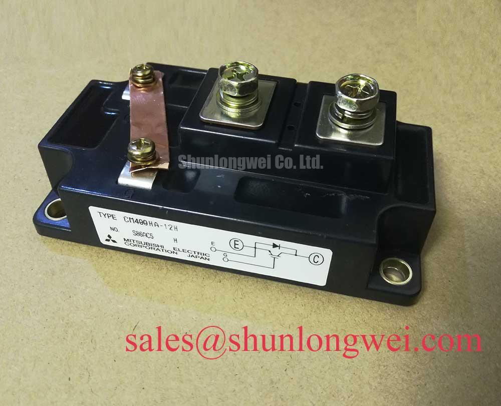
The Mitsubishi CM400HA-12H is a high-power, single IGBT module engineered for robust performance in demanding switching applications. This device integrates an IGBT and a reverse-connected, super-fast recovery free-wheel diode into an insulated package, focusing on reliable high-current operation and efficient thermal management. Its design provides a durable building block for power systems where proven performance and thermal stability are critical.
- Core Specifications: 600V | 400A | VCE(sat) 2.2V (typ)
- Key Advantages: Low conduction losses, excellent thermal dissipation via an isolated baseplate.
- Design Benefit: The module’s low thermal resistance simplifies heatsink selection and helps maintain junction temperatures within safe operating limits.
Download Official Datasheet (PDF)

Technical Analysis for System Integration
The engineering value of the CM400HA-12H is defined by key parameters that directly influence system efficiency and reliability. The collector-emitter saturation voltage (VCE(sat)) is specified at a typical value of 2.2V at the nominal 400A collector current (Tj=125°C). This parameter is a primary determinant of conduction losses. A lower VCE(sat) translates to less power dissipated as heat during the on-state, which is crucial for improving the overall efficiency of an inverter or motor drive.
Thermal performance is central to the module’s design. The thermal resistance from junction-to-case (Rth(j-c)) for the IGBT is a low 0.085°C/W. Think of thermal resistance as the width of a pipe for heat; a lower value signifies a wider pipe, allowing heat to escape more easily from the active semiconductor to the heatsink. This efficient heat evacuation is fundamental for maintaining the junction temperature below the 150°C maximum, ensuring long-term operational stability, particularly in high-power cyclic applications. For more on thermal design, see our guide on mastering the Zth curve.


Optimized Application Scenarios
The CM400HA-12H is specified for systems that require high-current capability and proven durability.
- AC Motor Control & VFDs: Its 400A continuous current rating is well-suited for driving large induction motors where robust performance under variable loads is essential.
- Welding Power Supplies: The module’s ability to handle a peak collector current of 800A (ICM) provides the necessary margin for the high-pulse demands of industrial welding equipment.
- Uninterruptible Power Supplies (UPS): The module’s reliability and isolated baseplate design contribute to building dependable inverters for critical power backup systems.
- Motion/Servo Control: In high-power servo applications, its defined switching characteristics enable precise and responsive motor control.
This module is a best-match for high-power, lower-frequency industrial applications where ruggedness and thermal performance are the primary design drivers.
Key Specifications of the CM400HA-12H
| Absolute Maximum Ratings (Tj = 25°C) | |
|---|---|
| Collector-Emitter Voltage (VCES) | 600V |
| Gate-Emitter Voltage (VGES) | ±20V |
| Collector Current (IC) | 400A |
| Peak Collector Current (ICM) | 800A |
| Maximum Collector Dissipation (Pc) | 1500W |
| Operating Junction Temperature (Tj) | -40 to +150°C |
| Isolation Voltage (Viso) | 2500Vrms |
| Electrical & Thermal Characteristics (Tj = 25°C unless noted) | |
| Collector-Emitter Saturation Voltage (VCE(sat)) @ 400A | 2.7V (max) |
| Gate-Emitter Threshold Voltage (VGE(th)) | 4V to 8V |
| Thermal Resistance, Junction to Case (Rth(j-c)) – IGBT | 0.085°C/W (max) |
| Thermal Resistance, Junction to Case (Rth(j-c)) – Diode | 0.16°C/W (max) |
Note: These parameters are highlights. For complete specifications, refer to the official datasheet.
Engineer’s FAQ
Q1: What is the maximum junction-to-case thermal resistance for the CM400HA-12H, and how does it affect heatsink selection?
The maximum thermal resistance for the IGBT is 0.085°C/W, and for the diode, it is 0.16°C/W. These low values signify efficient heat transfer from the semiconductor die to the module’s baseplate. For designers, this means a smaller temperature gradient between the junction and the case, which simplifies the selection of a heatsink required to keep the junction temperature below the 150°C maximum under a given load.
Q2: What are the recommended mounting torque specifications?
According to the datasheet, the main M6 terminals should be torqued to 1.96-2.94 N·m. The M4 gate/emitter terminals require 0.98-1.47 N·m, and the M6 module mounting screws also require 1.96-2.94 N·m. Adhering to these torque values is critical for ensuring both a reliable electrical connection and optimal thermal contact with the heatsink. Learn about the risks of improper torque in our technical articles.
Q3: Is the module’s baseplate electrically isolated?
Yes, all components and electrical interconnects are isolated from the heatsinking baseplate. The module is rated for an isolation voltage (Viso) of 2500Vrms (AC, 1 minute), which simplifies system assembly by allowing multiple modules to be mounted on a common, non-isolated heatsink. For further reading on this topic, explore our resources on power semiconductors.
Q4: What is the benefit of the included free-wheeling diode?
The integrated super-fast recovery free-wheel diode provides a path for inductive load current to flow when the IGBT is switched off. Its “soft” and fast recovery characteristics are essential for reducing voltage overshoots and electromagnetic interference (EMI), which is particularly important in motor drive and other inductive switching applications.
Enabling Reliable Power Systems
The Mitsubishi CM400HA-12H provides a foundation for high-power conversion systems that demand high-current capacity and proven durability. Its balance of electrical performance and thermal efficiency allows engineers to construct robust and reliable industrial equipment. The module’s straightforward, single-IGBT configuration and standard footprint facilitate both new designs and maintenance of existing systems.